


2-7
IN
OUT
REMOTE 2
AC IN
A
U
D
IO
AUD
IO OUT
R
R
/C
r
G
/Y
B
/C
b
V
H/HV
R
L/MONO
R
L/MONO
R
L/MONO
L/MONO
D
V
I
R
GB OUT
R
G
B
1
R
G
B
2
V
ID
E
O
S
-V
ID
E
O
A
U
D
IO
SLOT 1
S
LOT
2
4
3
IN
O
U
T
R
E
M
O
T
E
2
A
C
IN
A
U
D
I
O
A
U
D
IO
O
U
T
R
R
/
C
r
G
/
Y
B
/
C
b
V
H/H
V
R
L/MO
NO
R
L/MONO
R
L/MONO
L/M
ONO
D
V
I
R
G
B
O
U
T
R
G
B
1
R
G
B
2
V
ID
E
O
S-V
ID
EO
A
U
D
I
O
S
L
O
T
1
S
L
O
T
2
2
1
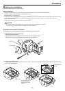
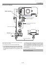
4. Reinstall the lens hood.
q Remove the front lens cap from the lens unit.
w Insert the lens hood so that the grooves on the 4 corners of the lens hood
are properly lined up with the 4 catches on the projector.
e Secure the 2 screws using the hexagonal driver.
This completes installation. If necessary, put the lens hood cap on the lens
hood.
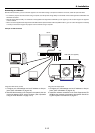
3
PC CONTROL
IN
IN
OUT
OUT
SC TRIGGER
REMOTE 2
REMOTE 1
LAN
AC IN
USB
(
M
O
U
S
E
/H
U
B
)
USB
(
PC
)
PC CARD
1
2
A
U
D
IO
AUDIO OUT
R
R
/C
r
G
/Y
B
/C
b
V
H
/H
V
R
L
/M
O
N
O
R
L
/
M
O
N
O
R
L
/M
O
N
O
L
/M
O
N
O
D
V
I
RGB OUT
R
G
B
1
R
G
B
2
V
ID
E
O
S
-
V
ID
E
O
A
U
D
I
O
SLOT 1 SLOT 2
2
P
C
C
O
N
T
R
O
L
I
N
I
N
O
U
T
O
U
T
S
C
T
R
I
G
G
E
R
R
E
M
O
T
E
2
R
E
M
O
T
E
1
L
A
N
A
C
I
N
U
S
B
(
MOUSE/HUB
)
U
S
B
(
P
C
)
P
C
C
A
R
D
1
2
AUDIO
A
U
D
I
O
O
U
T
R
R/Cr
G/Y
B/Cb
V
H
/
H
V
R
L
/
M
O
N
O
R
L
/
M
O
N
O
R
L
/
M
O
N
O
L
/
M
O
N
O
D
VI
R
G
B
O
U
T
R
G
B 1
RG
B 2
VID
EO
S
-V
ID
EO
AUDIO
S
L
O
T
1
S
L
O
T
2
1
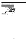
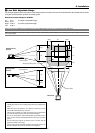
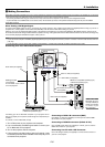
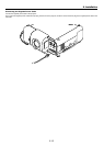
Lens shift defection switch
2. Installation
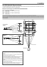
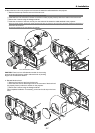
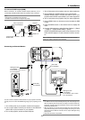
3. Mount the lens unit on the projector and connect the extension cable attached to the projector.
q Remove the lens cap from the rear end of the lens unit.
NOTE: Leave the front lens cap for protection while mounting the lens unit.
w Insert the lens unit so that the 4 screws on the lens unit are properly lined up with the 4 holes on the lens mount.
e Secure the 4 screws using the hexagonal driver.
r Insert the connector of the lens unit fully into the socket of the extension cable attached to the projector.
NOTE: The GT13ZL, GT19ZL, GT24ZL and GT34ZL optional lenses have one connector. The B type lenses (GT13ZLB, GT24ZLB and GT34ZLB) and
GT20ZL have two connectors.
To insert the connector into the 4-pin socket on the right side.
CAUTION: There is a lens shift detection switch for the moving
gears of the lens shift motors used to reduce the risk of pinching
fingers. Do not defeat this feature.