


IM01005012E XT-40 & IT-RSS Installation
Page 6 Rev. 1 – 2/2007
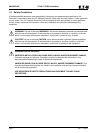
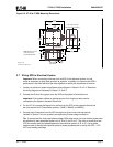
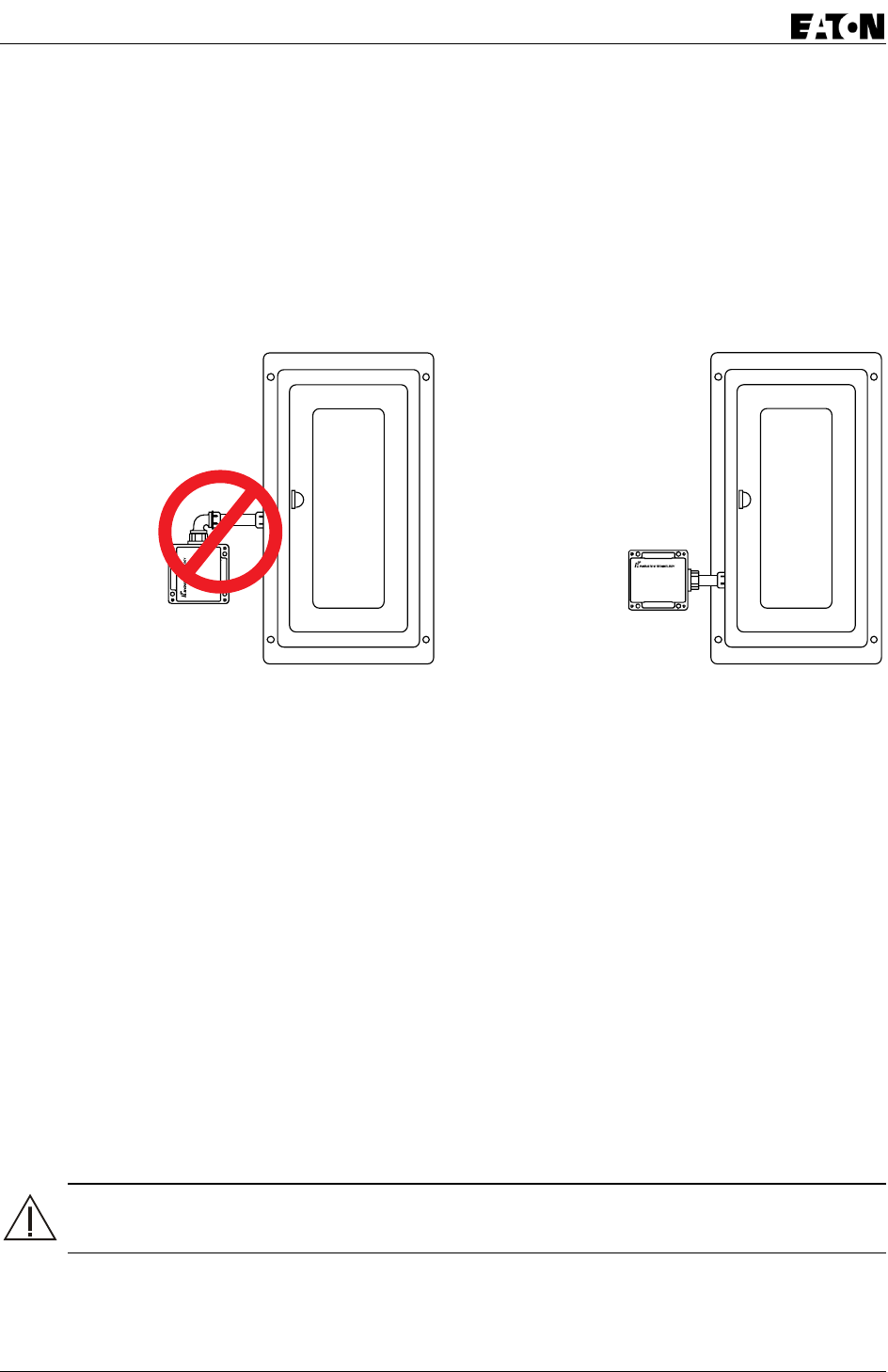
2.5 Conduit Installation
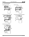
When planning the conduit installation, avoid using 90° elbows and keep the conduit run as short and
straight as possible. See Figure 2-1. When applicable, use weatherproof (corrosion resistant) conduit and
fittings to maintain the enclosure’s NEMA 4 or 4X rating.
If the system utilizes an isolated ground, then the SPD’s housing must be isolated from ground using
insulated conduit fittings.
Figure 2-1. Conduit Installation Guidelines
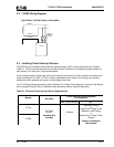
2.6 Mounting the SPD
The SPD is to be installed through a panel knockout and via its mounting feet. Place SPD against
mounting surface and mark feet positions. Complete conduit connection installation. Screw box to surface
with appropriate screws. Mounting dimensions and weight are shown in Figure 2-2.
Mount the SPD to provide the shortest and straightest possible wire installation from the SPD to the
system bus. Excessive wire length and sharp bends will degrade suppressor performance;
therefore, avoid excessive wire length and sharp bends when all possible.
If installing on a system other than an electrical panel, mount SPD in close proximity to the system being
protected using the necessary means for mounting.
Note: A circuit interrupt device is still required when installing suppressor on a
system other than an electrical panel.
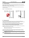
The SPD contains no position-oriented components and can be mounted upside down or sideways.
Cover may be rotated 180 degrees to improve label readability. Take care to support cover to prevent
damage to indicator light circuit board and wiring.
WARNING! Cover will not seal when rotated ONLY 90 degrees. This invalidates NEMA 4 rating
and may create safety hazard.
Avoid sharp bends in
wiring and longer than
necessar
y
wire len
g
ths
Keep wire lengths as
short and straight as
possible