


UPS 225 - 275 kVA
User’s and Installation Guide
1027212
Revision C
43
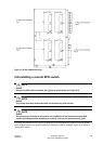
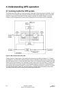
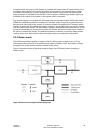
In bypass mode, the output of the system is provided with three-phase AC power directly from
the system input. While in this mode, the output of the system is not protected from voltage
or frequency fluctuations or power outages from the source. Some power line filtering and
spike protection is provided to the load but no active power conditioning or battery support is
available to the output of the system in the bypass mode of operation.
The internal bypass is comprised of a solid-state, silicon-controlled rectifier (SCR) static switch
(SSW) and a backfeed protection contactor K5. The static switch is rated as a continuous-duty
device that is used anytime the inverter is unable to support the applied load. The static switch
is wired in series with the backfeed protection contactor, and together they are wired in parallel
with the rectifier and inverter. The static switch, being an electronically-controlled device, can be
turned on immediately to pick up the load from the inverter while the inverter output contactor
K3 opens to isolates the inverter. The backfeed protection contactor is normally always closed,
ready to support the static switch unless the bypass input source becomes unavailable.
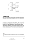
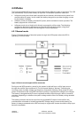
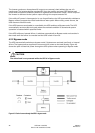
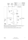
4.2.3 Battery mode
The UPS automatically transfers to battery mode if a utility power outage occurs, or if the
utility power does not conform to specified parameters. In battery mode, the battery provides
emergency DC power that the inverter converts to AC power.
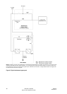
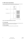
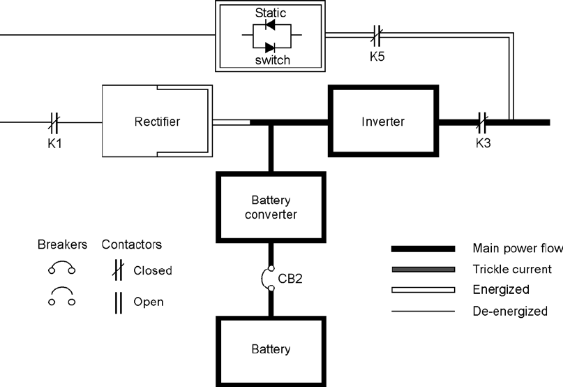
Figure 4-4 shows the path of electrical power through the UPS system when operating in
battery mode.
Figure 4-4. Path of current through the UPS in battery mode