


UPS 225 - 275 kVA
User’s and Installation Guide
1027212
Revision C
7
1.1.2 Customer Interface
Building Alarm Monitoring – Up to five inputs in the UPS are available to connect the •
facility’s alarm system contacts. Some system configurations may limit the number of
inputs available. The UPS uses these inputs to monitor the building alarms in addition to
the UPS status. See Chapter 7, “Communication,” for additional information.
Alarm Contact – One alarm contact is provided for connection to equipment at the facility, •
such as a light, an audible alarm, or a computer terminal. The equipment connected to
this contact alerts you to a UPS alarm. See Chapter 7, “Communication,” for additional
information.
X-Slot Communication Bay – A four-slot communication bay is standard equipment. •
Four optional X-Slot cards can be installed in the UPS module at any time. See Chapter 7,
“Communication,” for additional information.
ConnectUPS -X Web/SNMP Card – This X-Slot card is provided as standard equipment •
and provides remote monitoring through a Web browser interface, e-mail, and a network
management system (NMS) using SNMP. See Chapter 7, “Communication,” for additional
information.
1.1.3 Advanced Battery Management
A three-stage charging system increases battery service life by optimizing recharge time, and
protects batteries from damage due to high current charging and inverter ripple currents.
Charging at high currents can overheat and damage batteries.
1.1.4 Power Management Software
Powerware LanSafe® Power Management Software is bundled as part of the Software Suite CD
shipped with the UPS. See Chapter 7, “Communication,” for additional information.
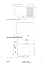
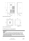
1.1.5 Installation features
Cabinets can be permanently bolted to the floor or left standing on leveling feet. Power and
control wiring can be routed through the top or bottom of the cabinet with connections made to
easily accessible terminals. External sensing and monitoring control wire must be installed in
accordance with Class 1 wiring methods. Line-up-and-match battery cabinets are wired through
the side panels of the units. Optional X-Slot connectivity cards are quickly installed at the front
of the unit and are hot-pluggable.
1.2 Options and accessories
Contact a Powerware sales representative for information about the following options.
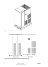
1.2.1 Integrated battery cabinet
Battery backup protection can be enhanced by equipping the UPS system with up to four
Powerware 9395 battery cabinets containing sealed lead-acid, maintenance-free batteries. The
battery cabinet is available in one size, with a 240-cell configuration. The cabinets are designed
for line-up-and-match installation, but may be installed separate from the UPS cabinet.
1.2.2 Optional X-Slot Cards
The optional X-Slot cards support several protocols, such as SNMP, HTTP, AS/400®, and
Modbus®. See Chapter 7, “Communication,” for additional information.