UPS 225 - 275 kVA
User’s and Installation Guide
1027212
Revision C
56
Set Date and Time
DD/MM/YYYY
The Set Date and Time DD/MM/YYYY screen allows the internal date and time
of the UPS to be set in the day/month/year format. The date and time informa-
tion is used for display on the screen and for logging events in the Event and
History Logs. Use the left or right arrow pushbuttons to highlight the setting to be
changed. Use the up or down arrow pushbuttons to make the change. When fin-
ished making changes, use the left or right arrow pushbuttons to highlight SAVE
and the up or down arrow pushbuttons to select YES. To complete the save func-
tion and return to the System Setup screen, select the return arrow pushbutton.
Com Port Selection The Com Port Setup screen allows selection of the serial COM port to set up.
Select COM PORT SETUP from the System Setup Level 1 menu to display the
COMPort Setup screen. Use the up or down arrow pushbuttons to highlight the
the COM port to be set up, then press the SELECT pushbutton. To return to the
System Setup screen, press the return arrow pushbutton.
Com Port Setup The COM Setup screen is used to change and save the settings for the selected
serial communication port. The COM port number selected from the COM Port
Setup screen displays. If the changes are not wanted, use the ABORT pushbut-
ton to return to the COM Port Setup screen. Use the up or down arrow pushbut-
tons to highlight the setting to be changed. Use the return arrow pushbutton
to toggle through the values for the setting to make the change. Press SAVE or
ABORT. Once the action is completed, the COM Port Setup screen appears.
Control See paragraph 5.2.6 for details.
Table 5-3. Display menu operation
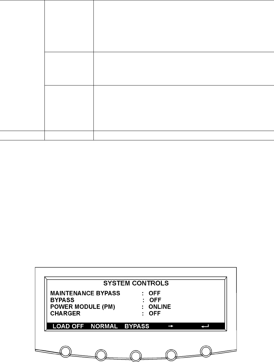
5.2.6 System controls screen
Press the CONTROLS pushbutton on the main menu bar to display the System Controls screen.
LOAD OFF, normal operation, transfer to bypass, charger control, and power module startup and
shutdown functions are controlled from this screen. In addition, the screen displays the current
status of the UPS and indicates whether the UPS is in Maintenance Bypass or Bypass, and the
state of the power module (PM) and battery charger. Figure 5-5 and Figure 5-6 show the System
Controls screens.
Use the or pushbutton on the menu bar to toggle the menu bar functions between the two
System Controls screens.
For detailed information about using the System Controls, see paragraph 5.3.
Figure 5-5. System Controls screen 1


