


For more information visit: www.eaton.com IB00405004E-70-8664
Instructional Booklet
Page 4 Effective: June 2007
Instruction Manual for the Eaton RTC-50
Automatic Transfer Switch Controller
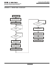
26. Utility - Monitoring and Protection
This feature provides Utility monitoring and protection
functions. If the Utility power source fails, then the RTC-
50 will begin the sequence of operations necessary to
transfer the load circuit to the Generator power source.
All Feature 26 monitoring and protection functions are fail-
safe operations.
26D. Go To Generator
This feature provides the capability for an external contact
closure to initiate a transfer from Utility to Generator.
After the Generator becomes available, TDNE will time out
before the transfer to Generator takes place. Re-transfer
will occur when the external contact is opened or under a
failsafe condition. A connection point for the connection
of an external contact is provided.
26P. All Phase Undervoltage Protection
Dropout: 168 Vac (70% of 240 Vac nominal)
Pickup: 192 Vac (80% of 240 Vac nominal)
SECTION 2:HARDWARE DESCRIPTION
2.1 General
The purpose of this section is to familiarize the reader with the
RTC-50 controller hardware, its nomenclature, and to list the
unit’s specifications.
2.2 LED Indicators
• Utility Available
The green Utility Available LED illuminates if the utility power
source meets the criteria to be considered “available”. That is,
when it is within its undervoltage range.
• Generator Available
The red Generator Available LED illuminates if the generator
power source meets the criteria to be considered “available”.
That is, when it is within its undervoltage range.
2.3 Programming Jumpers
The RTC-50 controller is programmable via two jumpers on the PC
board. The jumper selections are discussed in Section 4, Program-
ming.
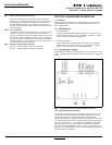
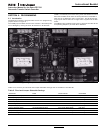
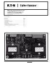
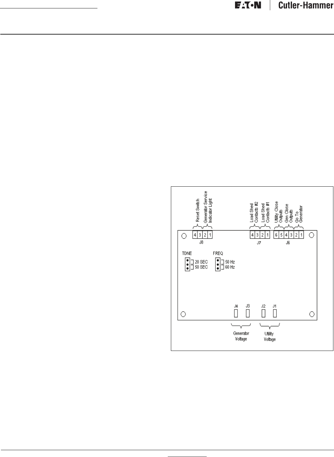
Figure 1. RTC-50 Connectors and Programming Jumpers.
2.4 Input/Output Connectors
Located along the bottom of the RTC-50 are connectors J1, J2,
J3, and J4. J1 and J2 provide for voltage monitoring of utility.
J3 and J4 provide for voltage monitoring of the generator.
Located along the top of the RTC-50 are connectors J6, J7, and
J8. J6 provides connections for the control input and the transfer
switch control outputs. J7 provides load shedding connections
for the customer to use. J8 provides connections to a remote
light to indicate that generator service is due. A pushbutton can
be wired to the Reset Switch input to acknowledge and reset the
Generator Service indication.