


For more information visit: www.eaton.com IB00405004E-70-8664
Instructional Booklet
Page 6 Effective: June 2007
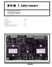
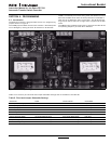
Instruction Manual for the Eaton RTC-50
Automatic Transfer Switch Controller
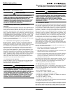
2.7 Specification Summary
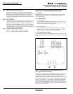
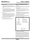
Table 1. RTC-50 Controller Specifications
SECTION 3: OPERATION
3.1 General
This section specifically describes the operation and functional use
of the RTC-50 controller. The practical use of and operation
within each category will be discussed. In this section, it is
assumed that prior sections of this manual were reviewed and
that the operator has a basic understanding of the hardware.
The RTC-50 controller provides for automatic transfer and re-
transfer from source to source. It provides a summary of the
RTC-50 controller intelligence and supervisory circuits that con-
stantly monitor the condition of both the Utility and Generator
power sources, thus providing the required intelligence for transfer
operations. These circuits, for example, automatically initiate an
immediate transfer of power when the power fails or the voltage
level drops below a preset value and an alternate source of power
is available.
3.2 Operating Voltage and Measurements
The RTC-50 controller operates on an input voltage of 240 Vac
with selectable frequency settings of 50 or 60 Hz.
The RTC-50 controller operates directly from the line sensing
inputs of the Utility and Generator power sources.
All voltage monitoring and measurements are true RMS measure-
ments.
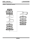
3.3 Typical Transfer Operation
A typical transfer request will begin with a Utility outage (Utility
voltage falls below the 70% dropout level).
When the Generator source meets the requirements to be consid-
ered available, the TDNE (Time Delay Normal to Emergency) timer
will start timing. TDNE is jumper-programmable at either 20 sec-
onds or 50 seconds. The 50 second setting may be used to allow
for a longer warm-up period of the Generator. After TDNE times
out, the Utility Close Outputs will open, the Gen Close Outputs
will close, and the Load Shed Contacts will open. This will con-
nect the load to the Generator source but any loads wired to the
Load Shed Contacts will be disconnected.
When the Utility becomes available (Utility voltage is above the
80% pickup level), the TDEN (Time Delay Emergency to Normal)
timer will start timing. TDEN is a fixed delay of 10 seconds. After
TDEN times out, the Gen Close Outputs will open, the Utility
Close Outputs will close, and the Load Shed Contacts will be
closed. This will connect all loads to the Utility source.
INPUT VOLTAGE 240 VAC 50/60 HZ
Voltage Measurements of Utility Generator
Voltage Measurement Range 0 to 300 Vac RMS (50/60 Hz)
Voltage Measurement Accuracy ± 6 Vac
Undervoltage Dropout 70% of the Nominal 240 Vac Input Voltage
Undervoltage Pickup 80% of the Nominal 240 Vac Input Voltage
Operating Temperature Range -20 to +70°C (-4 to +158°F)
Storage Temperature Range -30 to +85°C (-22 to +185°F)
Operating Humidity 0 to 95% Relative Humidity (Non-condensing)
Operating Environment Resistant to Ammonia, Methane, Nitrogen, Hydrogen,
and Hydrocarbons
Utility Close and Gen Close Outputs 5 amps @ 250 Vac
5 amps @ 30 Vdc
Load Shed Contacts #1 and #2 5 amps @ 250 Vac
5 amps @ 30 Vdc
Applicable Testing UL Recognized Component
UL 1008, UL 991 Environmental
IEC 61000-4-2, 61000-4-3, 61000-4-4, 61000-4-5,
61000-4-6, 61000-4-11
CISPR 11, Class B
FCC Part 15, Class B