


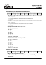
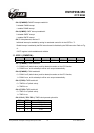
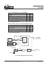
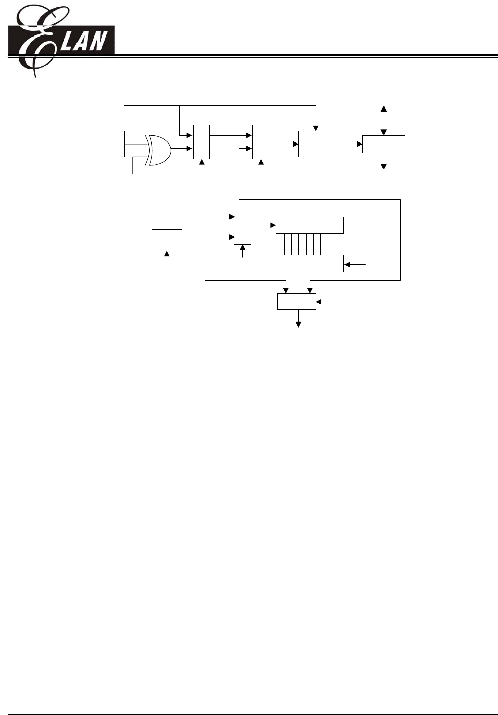
EM78P458/459
OTP ROM
8-bit Counter
8-to-1 MUX
MUX
M
U
X
WDT
TCC
Pin
M
U
X
M
U
X
SYNC
2 cycles
TCC (R1)
PAB
PAB
PAB
TSTE
0
0
1
1
1
0
WDTE
(in IOCE)
WDT timeout
PSR0 ~ PSR2
0
1
DATA BUS
CLK (Fosc/2 or Fosc/4)
TCC overflow
interrupt
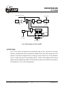
Fig. 5 Block Diagram of TCC and WDT
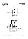
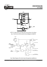
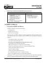
4.4 I/O Ports
Port 5, Port 6, and the I/O registers are bi-directional tri-state I/O ports. The function of Pull-high,
Pull-down, and Open-drain can be set internally by IOCB0, IOCC0, and IOCD0, respectively. Port 6
features an input status changed interrupt (or wake-up) function. Each I/O pin can be defined as
"input" or "output" pin by the I/O control register (IOC50 ~ IOC60). The I/O registers and I/O control
registers are both readable and writable. The I/O interface circuits for Port 5 and Port 6 are shown in
the following Fig. 6, Fig. 7, and Fig. 8 respectively.
This specification is subject to change without prior notice. 07.01.2003 (V1.3)
23