


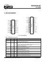
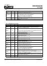
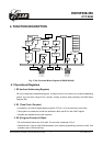

EM78P458/459
OTP ROM
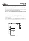
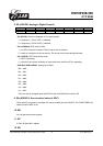
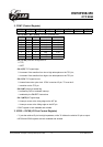
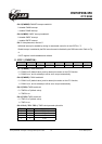
2. CONT (Control Register)
7 6 5 4 3 2 1 0
INTE INT TS TE PAB PSR2 PSR1 PSR0
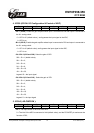
• Bit 0 (PSR0) ~ Bit 2 (PSR2) TCC/WDT prescaler bits.
PSR2 PSR1 PSR0 TCC Rate WDT Rate
0 0 0 1:2 1:1
0 0 1 1:4 1:2
0 1 0 1:8 1:4
0 1 1 1:16 1:8
1 0 0 1:32 1:16
1 0 1 1:64 1:32
1 1 0 1:128 1:64
1 1 1 1:256 1:128
• Bit 3 (PAB) Prescaler assignment bit.
0: TCC;
1: WDT.
• Bit 4 (TE) TCC signal edge
0: increment if the transition from low to high takes place on the TCC pin;
1: increment if the transition from high to low takes place on the TCC pin.
• Bit 5 (TS) TCC signal source
0: internal instruction cycle clock. If P54 is used as I/O pin, TS must be 0.
1: transition on the TCC pin
• Bit 6 (INT) Interrupt enable flag
0: masked by DISI or hardware interrupt
1: enabled by the ENI/RETI instructions
• Bit 7 (INTE) INT signal edge
0: interrupt occurs at the rising edge on the INT pin
1: interrupt occurs at the falling edge on the INT pin
• CONT register is both readable and writable.
3. IOC50 ~ IOC60 (I/O Port Control Register)
• "1" puts the relative I/O pin into high impedance, while "0" defines the relative I/O pin as output.
• IOC50 and IOC60 registers are both readable and writable.
This specification is subject to change without prior notice. 07.01.2003 (V1.3)
14