


EM78P458/459
OTP ROM
CONTW
MOV A, @0B00000000 ; To employ Vdd as the reference voltage, to define P60 as
IOW ADCONC ; an analog input and set clock rate at fosc/4
En_ADC:
MOV A, @0BXXXXXXX1 ; To define P60 as an input pin, and the others are dependent
IOW PORT6 ; on applications
MOV A, @0B01000101 ; To enable the OP1, and set the gain as 32
IOW GCON
BS ADCONR, ADPD ; To disable the power-down mode of ADC
ENI ; Enable the interrupt function
BS ADCONR, ADRUN ; Start to run the ADC
; If the interrupt function is employed, the following three lines may be ignored
POLLING:
JBC ADCONR, ADRUN ; To check the ADRUN bit continuously;
JMP POLLING ; ADRUN bit will be reset as the AD conversion is completed
(User program)
:
:
:
4.8 Dual Sets of PWM ( Pulse Width Modulation )
1. Overview
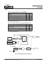
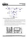
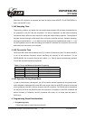
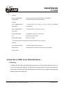
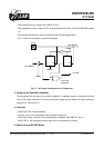
In PWM mode, both PWM1 and PWM2 pins produce up to a 10-bit resolution PWM output (see. Fig.
13 for the functional block diagram). A PWM output has a period and a duty cycle, and it keeps the
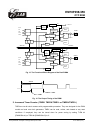
output in high. The baud rate of the PWM is the inverse of the period. Fig. 14 depicts the relationships
between a period and a duty cycle.
This specification is subject to change without prior notice. 07.01.2003 (V1.3)
37