


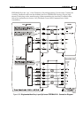
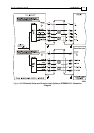
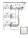
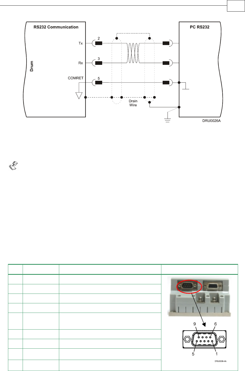
Figure 3-27: RS-232 Connection Diagram
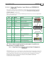
3.4.8.2 CANopen Communication
Notes for connecting the CANopen communication cable:
Use 24, 26 or 28 AWG twisted pair shielded cables (24 AWG cable is recommended).
For best results, the shield should have aluminum foil and covered by copper braid
with a drain wire
Connect the shield to the ground of the host (PC). Usually, this connection is
soldered internally inside the connector at the PC end. You can use the drain wire to
facilitate connection.
Use only a D-sub connector with a metal housing.
Attach the braid shield tightly to the metal housing of the D-type connector.
Connect a termination 120-ohm resistor at each of the two ends of the network cable.
When assembling the Communication cable, follow the instructions in Section
3.4.3
(Feedback Control and Communication Cable Assemblies).
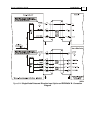
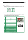
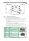
Pin Signal Function Pin Position
1 — —
2 CAN_L CAN_L busline (dominant low)
3 CAN_GND CAN ground
4 — —
5 CAN_SHLD Shield, attach to the metal housing of
the D-type
6 CAN_GND CAN Ground
7 CAN_H CAN_H busline (dominant high)
8 — Do not connect
9 — Do not connect
Table 3-15: CANopen Cable - Pin Assignments
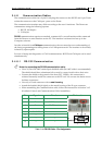
J1
Male
Drum Installation Guide Installation
MAN-DRUIG (Ver. 1.0)
3-43