


8
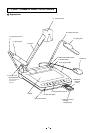
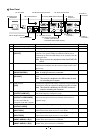
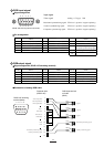
Rear Panel
OUTPUT
MOUSE CONTROL
AC IN
INPUT
RS-232C
OUTPUT
12V 0.9A
USB
RGB OUT
S-VIDEO
R
L
AUDIO
VIDEO
RGB1
RGB2
AUDIO(L/R)1
AUDIO(L/R)2
26. Power Cord
Receptacle
38. Audio-in
Terminal 1
39. Audio-in
Terminal 2
31. RS-232C Terminal
36. Video-in
Terminal 1
29. Infrared Sensor
28. DC Output Terminal
30. Mouse Control Terminal27. AC Outlet
32. USB Terminal
33. Analog RGB Output Terminal
34. Video-out Terminal
S-Video (mini DIN 4P)/
Composite-Video (RCA pinjack)
35. Audio-out Terminal
37. Video-in
Terminal 2
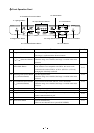
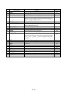
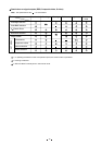
Part Name Function
Reference Page
26
Power Cord Receptacle [AC IN]
To connect the power cord.
27 AC Outlet To supply power up to 400W (Not interlocked with the power switch).
28 DC Output Terminal To output 12VDC. Any applicable equipment up to 0.9A can be
[OUTPUT]
connected. The optional LCD Color Monitor (LM-5011N) or
ELMO Desk-top Presenter (HD-80XG) can be connected with the
supplied DC cable.
Note: Do not connect any equipment other than ELMO HD-
80XG.
29 Infrared Sensor The light receiver of the wireless remote control. When operating
the Presenter from behind, aim the wireless remote control at this
light receiver.
30 Mouse Control Terminal To connect the supplied mouse.
[MOUSE CONTROL]
Note: A serial type mouse is connected.
31 RS-232C Terminal To connect a PC with an RS-232C cable to control the Presenter from
[RS-232C] the PC.
Note: This terminal is disabled if the USB terminal is used
for controlling the Presenter.
32 USB Terminal To connect the supplied USB cable to control the image transfer and
[USB]
the Presenter by using the supplied CD-ROM [Image Mate for USB].
Note: This terminal is disabled if the RS-232C terminal is
used for controlling the Presenter.
33 Analog RGB Output Terminal To connect RGB input equipment, such as an LCD Projector and a
[OUTPUT•RGB OUT]
Multi-SYNC Monitor, to output the image.
34 Video-out Terminal To connect a NTSC/PAL conformable monitor, such as a TV
[OUTPUT•
S-VIDEO/VIDEO
] monitor and the optional LCD Color Monitor (LM-5011N), to
S-Video (mini DIN 4P) output the image.
Composite-Video (RCA pinjack)
35 Audio-out Terminal To connect audio input equipment to output the audio.
[OUTPUT•AUDIO]
36 Video-in Terminal 1 Video signal from this terminal is output through the analog RGB
[INPUT
•
RGB1]
output terminal when input selection is set at RGB1.
37 Video-in Terminal 2 Video signal from this terminal is output through the analog RGB
[INPUT
•
RGB2]
output terminal when input selection is set at RGB2.
38 Audio-in Terminal 1 Audio signal from this terminal is output through the audio-out
[INPUT•AUDIO (L / R)1] terminal when input selection is set at RGB1.
39 Audio-in Terminal 2 Audio signal from this terminal is output through the audio-out
[INPUT•AUDIO (L / R)2] terminal when input selection is set at RGB2.
P.11
P.31