


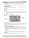
Electrical Connections
16
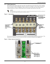
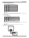
2.3.2 Maintenance Bypass Cabinet Interface
J26 and J30 are the MBC interface.
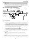
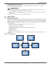
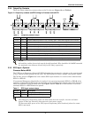
2.3.3 BCB Box Interface
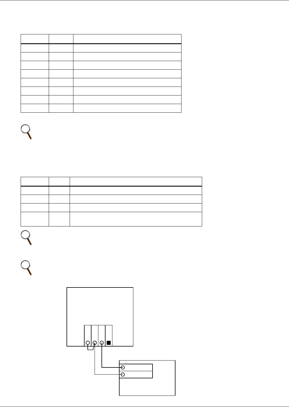
J10 is the BCB box interface.
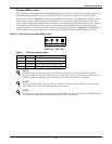
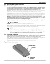
Figure 9 Jumper connection for BCB interface
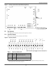
Table 2 Maintenance bypass cabinet interface
Position Name Description
J26.1 T_IT
1
Input transformer over temperature (N.C.)
J26.2 AUX_I Reserved
J26.3 +12V +12V Power
J26.4 GND Power Ground
J30.1 FUSE Reserved
J30.2 F_FAN Fan Fail Alarm (N.C.)
J30.3 T_OT
1
Output Transformer Overtemperature (N.C.)
J30.4 AUX_O Reserved
1 - Must be configured by software before becoming active
NOTE
All auxiliary cables of terminal must be double-insulated. Wire should be 20-16AWG stranded
for maximum runs between 82 and 164 feet (25-50m), respectively.
Table 3 BCB box interface
Position Name Description
J10.1 DRV BCB Driver Signal - Reserved
J10.2 FB BCB Contact State
J10.3 GND Power Ground
J10.4 OL
BCB On-Line - Input - This pin will become active when
BCB interface is connected. (N.O.)
NOTE
All auxiliary cables of terminal must be double-insulated. Wire should be 20-16AWG stranded
for maximum runs between 82 and 164 feet (25-50m), respectively.
NOTE
If BCB interface is connected, a jumper needs to added between Pin 3 and Pin 4.
UPS Monitoring Board
J10
OL
DRV
GND
FB
Battery Circuit Breaker
OL
Aux – N.O.
Aux – N.O.