


Installation Drawings
53
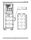
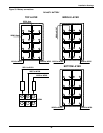
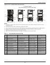
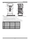
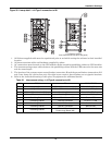
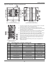
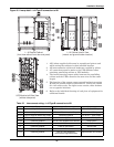
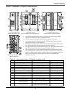
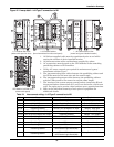
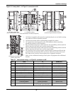
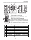
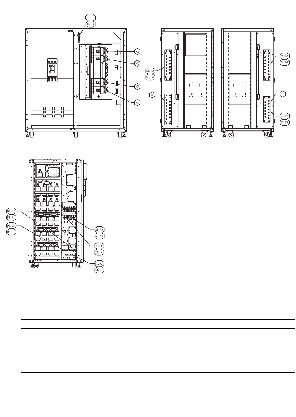
Figure 40 Lineup detail—1+N Type B connection to NX
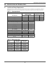
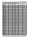
Table 22 Interconnect wiring—1+N Type B connection to NX
Run From To Conductors
A1-A4 Utility AC Source UPS #1-UPS #4 Module AC Input Ph A, B, C - UPS Input
B1-B4 Utility AC Source UPS #1-UPS #4 Module AC Input Neutral - UPS Input
C1-C4 UPS #1-UPS #4 Module AC Output Paralleling Cabinet Ph A, B, C - UPS Output
D1-D4 UPS #1-UPS #4 Module AC Output Paralleling Cabinet Neutral - UPS Output
E1-E4 Paralleling Cabinet UPS #1-UPS #4 Module AC Ground Ground-UPS
F Paralleling Cabinet Load AC Connection Ph A, B, C - Load
G Paralleling Cabinet Load AC Connection Ground-load
H Paralleling Cabinet Load AC Connection Neutral-load
I1-I4
Paralleling Cabinet
UPS #1-UPS #4 Module
UPS Parallel Logic Board (M3)
Output Breaker Aux Contact
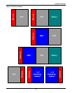
1 + N Parallel Cabinet
(front view without front door and panel)
1 + N Cabinet Interior View
(neutral and ground busbar location)
UPS Module Left Side View
(without side panel)
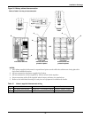
I1, I2
1. All Liebert-supplied cable must be repositioned prior to and
while setting the cabinets in their installed location.
2. All interconnection cables and hardware supplied by others.
3. AC connections must be made to the UPS modules before
attaching paralleling cabinet to UPS modules.
4. The interconnecting output cables between the paralleling
cabinet and the UPSes must be the same size and the same
length.
5. The location of the system output neutral busbar (connection
K) and the ground busbar (connections H, I and J) are shown
for a left-access style. For right-access version, these busbars
are at opposite locations.
6. Refer to the individual drawing of each piece of equipment for
additional details.