Battery Installation
22
3.4.3 Installation Considerations
Position—Liebert battery cabinets come in versions specific to either the left or right side of the
UPS. Control wires and power cables are cut to different lengths for the different versions. If the sys-
tem includes a matching maintenance bypass cabinet (MBC), the MBC should be mounted to the left
of the UPS (nearest the busbars) and the battery cabinet(s) should be installed to the right of the
UPS. Otherwise, left-side placement of the battery cabinet is preferable.
The battery cabinet(s) are designed to be located conveniently next to each UPS module, and are also
available in stand-alone configurations with painted side panels. The front access design eliminates
side and rear service clearance requirements. Refer to Table 33 for battery cabinet dimensions and
weights.
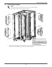
Bolt-On Cabinets—Matching battery cabinets are designed to bolt onto the side of the UPS module
cabinet. Use bolts that ship with each unit to connect cabinet frames at posts, two places in the front
and two places in the rear.
Service Clearance—Allow front access to the battery cabinet at all times for maintenance and ser-
vicing. Electrical codes require that the battery cabinet be installed with no less than 3 feet (1m) of
clearance at the front of the cabinet when operating. Side and rear panels do not require service clear-
ance.
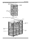
Cables—Cables may be run between the cabinets through cutouts in the top of the cabinet, eliminat-
ing the need for external conduit runs. Route cables before moving cabinets into final position for bolt-
ing together. No top or bottom entry cables are required, except for remotely located cabinets which
require conduits. Refer to Figure 15.
Software—To allow the UPS to accurately display the battery run time, the number of battery cabi-
nets must be noted when performing initial startup and setup using the configuration software. This
is to be performed by the Liebert Global Services customer engineer when commissioning the unit.
Casters and Adjustable Stops—The adjustable stops are not designed to bear the full weight of the
cabinet. Lower the stops until they are finger-tight in contact with the floor. Then tighten a small
amount with a wrench (less than two turns) to give a good friction fit. When mounting the battery
cabinet on seismic stands, ensure that the casters are bearing the weight of the cabinet.
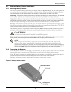
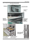
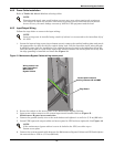
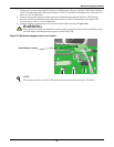
Battery Support Tray—Be sure to connect the battery tray support to the front of the cabinet
before sliding a battery tray out for connection or service. Without the support, the battery tray may
fall out of the cabinet. See Figure 16 for details.


