


Electrical Connections—UPS
35
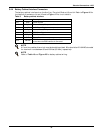
3.4.4 Battery Cabinet Interface Connectors
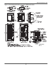
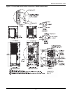
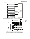
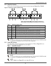
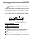
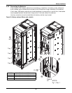
The battery cabinet interface is on the Auxiliary Terminal Block at J8 and J4. Refer to Figure 16 for
the location of connectors J4 and J8 and to Figure 17 for circuit details.
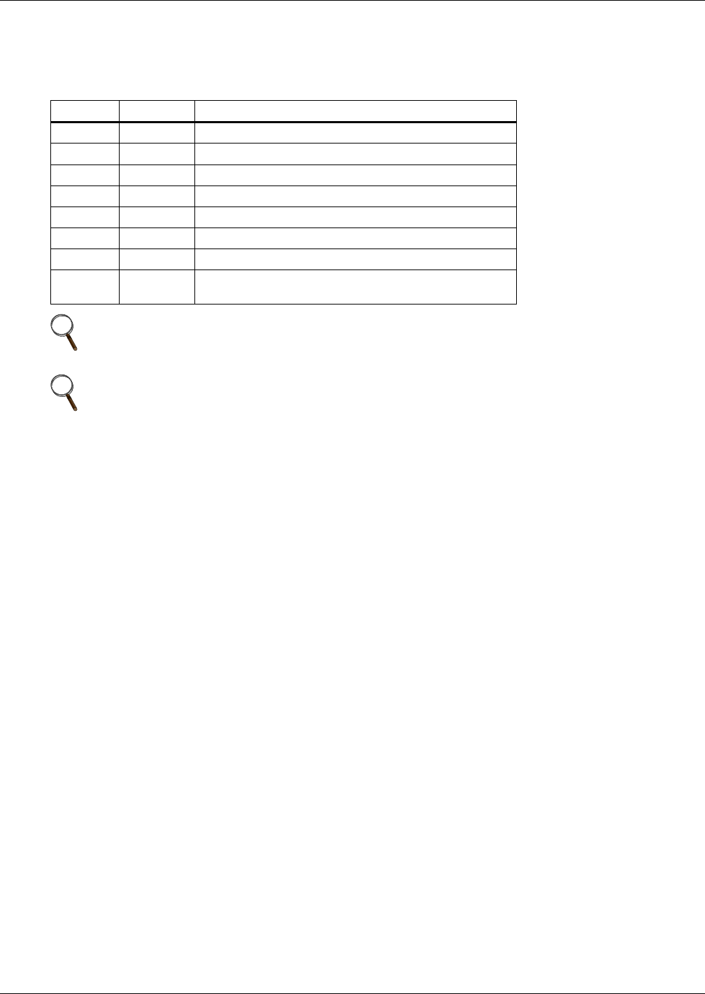
Table 8 Battery cabinet interface
Position
Name
Description
J4.1 GND Power Ground
J4.2 BAT_OUT External Battery Temperature Detection
J4.3 +12V +12V Power Supply
J4.4 BAT_IN Internal Battery Temperature Detection
J8.1 DRIVER BCB Driver Signal
J8.2 BCB_IN BCB Contact State
J8.3 GND Power Ground
J8.4 ONLINE
BCB On-Line - Input (N.O.) - This pin will become
active when the BCB interface is connected.
NOTE
All auxiliary cables of terminal must be double-insulated. Wire should be 20-16AWG stranded
for maximum runs between 80 and 200 feet (25-60m), respectively.
NOTE
Refer to Table 10 and Figure 23 for battery cabinet wiring.