


Liebert
®
BDC
™
47
5.4.2 Power Cable Installation
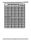
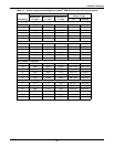
Refer to Table 43 when selecting cables.
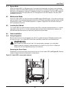
5.4.3 Input/Output Wiring
Follow the steps below to connect the input wiring:
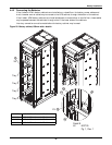
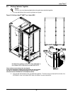
1. Locate the input wiring access (top or bottom access), remove the conduit landing plate and punch
the appropriate size hole for the size conduit being used. Pull the three/four input wires through
it, allowing some slack for installation. For cabinets that are located to the immediate left of the
UPS, the access plate is on the lower right of the cabinet. Remove the access plate and verify that
the edge guarding is installed and intact.
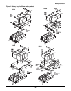
2. Secure the conduit to the access plate of the Liebert BDC.
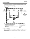
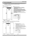
3. Input power cables connect to the system input circuit breaker; refer to Figure 41 and to
Table 18.
4. Connect the ground (earth) wire to the earth busbar and tighten it to 240lb-in. (27N-m) (M10
bolt).
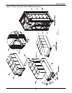
5. Locate UPS input and output cables and access panel to UPS on lower right side.
6. Connect the system ground cable between the Liebert BDC and UPS and tighten the connections
to 240lb-in. (27N-m) (M10 bolt).
7. Connect the system input cables between the Liebert BDC “UPS Input” Busbars (A-B-C N
terminals) and UPS input busbars (A-B-C N terminals) and tighten the connections to 240lb-in.
(27N-m) (M10 bolt).
8. Connect the system output cables between the Liebert BDC 'UPS Output' Busbars (A-B-C N
terminals) and UPS output busbars (A-B-C N terminals) and tighten the connections to 240lb-in.
(27N-m) (M10 bolt).
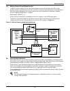
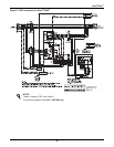
9. Connect TB1 from the Liebert BDC to J5 and J12 on the Liebert
®
APM
™
.
NOTICE
Risk of improper wiring connection. Can cause equipment damage.
The control wire must be installed to ensure proper operation of the system and fully protect
the load when switching between bypass cabinet and UPS.
NOTE
Transient and steady state earth leakage currents may occur when starting the equipment.
This should be taken into account when selecting ground current detection devices because
these will carry the earth leakage currents of both the UPS equipment and the load.
NOTE
Input wiring must be installed using conduit if cabinet is not mounted to the immediate right
of the UPS.
NOTE
If the Liebert BDC is not to be bolted to the UPS, use either top or bottom access plate.
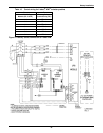
Table 11 Control wiring for Liebert APM UPS to Liebert BDC
From To
Liebert APM UPS Bypass
Module (X2 J5 & J12) Liebert BDC Terminal Strip (TB1)
J12-3 TB1-11
J12-4 TB1-12
J5-1 TB1-3
J5-3 TB1-6
J5-4 TB1-5
Jumper TB1-4 to TB1-5