


Electrical Connections—UPS
36
3.4.5 EPO Input—Optional
NOTICE
Risk of exceeding internal voltage limits. Can cause equipment damage.
Do not apply more than 12V to the Emergency Power Off (EPO) input. Exceeding 12V on this
input can damage the Liebert APM’s internal circuitry and control boards. Exceeding 12V will
also put the Liebert APM in an EPO state, and the unit will not reset, making it non-
functional.
The UPS has an Emergency Power Off (EPO) function operated by a button on the control panel or by
a remote contact provided by the user. The EPO button is under a hinged, clear plastic shield.
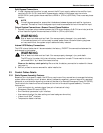
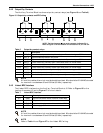
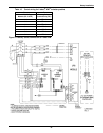
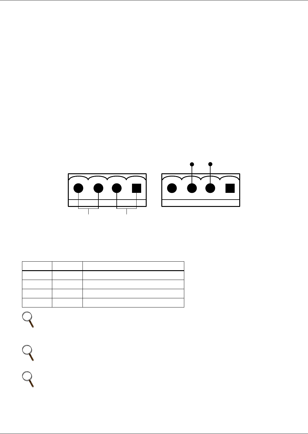
The J6 connector, shown in Figure 19, is the remote EPO input interface. The EPO has NO/NC
contacts that become active when shorting terminals J6: 3 and 4 or open terminal connection J6: 2
and 1.
If an external Emergency Stop capability is required, it is connected at terminals J6: 1 and 2 and at
J6: 3 and 4 on the monitor board. It also is connected to the Normally Open or Normally Closed
remote stop switch between these two terminals using shielded cable (see Figure 19 and Table 9). If
this function is not used, terminals J6:3 and 4 must be opened and J6:1 and 2 must be closed.
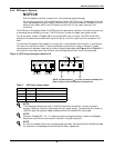
Figure 19 EPO wiring and signal names for J6
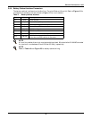
Table 9 EPO input contact relays
Position Name Description
J6.1 EPO_NC EPO Activated when opened to J6.2
J6.2 +12V EPO Activated when opened to J6.1
J6.3 +12V EPO Activated when shorted to J6.4
J6.4 EPO_NO EPO Activated when shorted to J6.3
NOTE
The Emergency Stop action within the UPS shuts down the rectifier, inverter and static
bypass. It does not internally disconnect the input power supply. To disconnect ALL power to
the UPS, open the upstream feeder breaker(s) when the remote EPO is activated.
NOTE
Normally Closed EPO – J6: 1, 2, these terminals are supplied factory-linked on the Bypass
Module on the UPS and must remain installed if using NO contacts.
NOTE
All auxiliary cables of terminal must be double-insulated. Wire should be 20-16AWG stranded
for maximum runs between 80 and 200 feet (25-60m), respectively.
J6
EPO-NO EPO-NC
J6
EPO-NO
EPO-NC
+12V +12V
+12V
+12V
NOTE: The black square () on each connector indicates Pin 1.
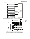
Refer to Figure 16 for the location of connector J6.