


Electrical Connections—UPS
32
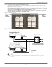
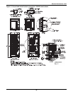
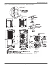
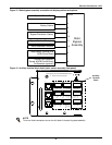
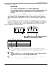
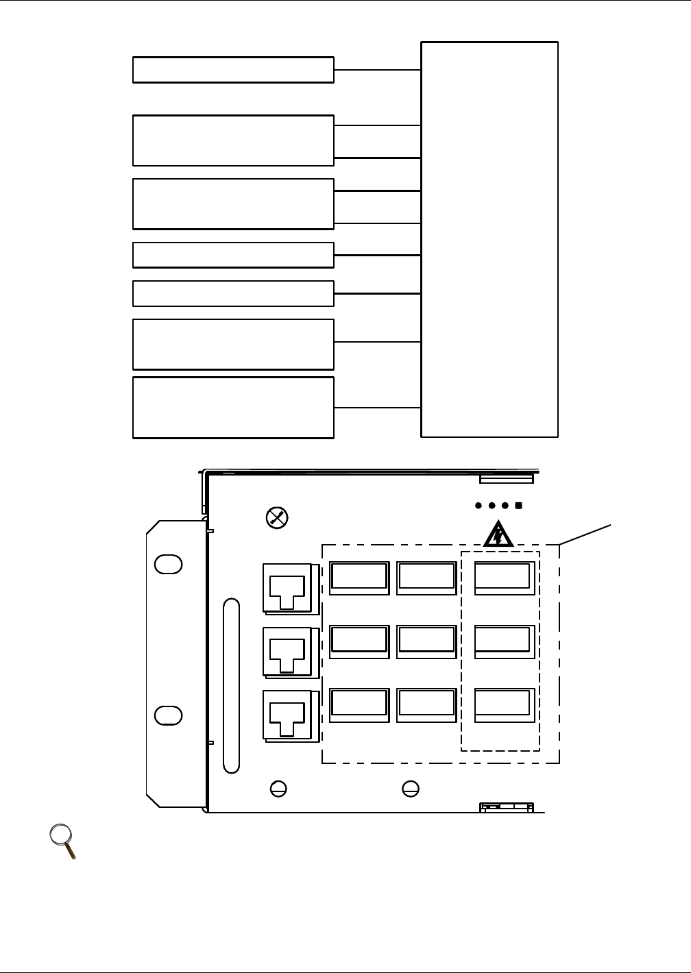
Figure 15 Static bypass assembly connections to display cabinet and options
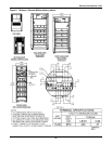
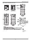
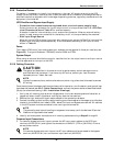
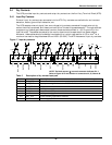
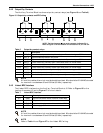
Figure 16 Auxiliary terminal block detail (static switch assembly front panel)
NOTE
Terminal block connectors are on the left side of the static bypass assembly.
Monitor
J4
J8
J5
J12
J11
J10
J4
J9
Operator Control Panel
Battery Cabinet
Bypass Distribution Cabinet
Temp Sensor (optional) and
BCB Control Board
Ground Fault (optional)
Sensor & BCB Control Board
On Generator (optional)
Static
Bypass
Assembly
Mains Backfeed Protection
Bypass Backfeed Protection
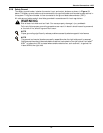
J1 J3 port can't connect to phone !
Input/output dry contact and EPO/BCB/MBC interface
J1
J4 J7 J10
MFP_O
MFP_S
MFP_C
J11
INPUT_2
INPUT_1
OUT
GND
J8
+12V
BAT-IN
BAT-OUT
GND
J5
PA RAJ2
BCB_IN
DRIVER
GND
ONLINE
Q2BP
Q3BP
EXT-OUT
GND
J9J6
J3 PARA
BFP_O
BFP_S
BFP_C
J12
INV_O
INV_S
INV_C
BAT_GND
ENV_DET
BAT_READY
+12V
+12V
EPO-NC
+12V
EPO-NO
LBS
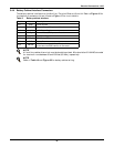
Auxiliary
Terminal
Block