


Battery Installation
42
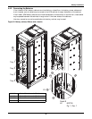
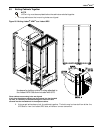
4.4.3 Installation Considerations
Position—Liebert battery cabinets come in versions specific to the left side of the UPS. If the system
includes a matching Liebert BDC, the cabinet should be mounted to the right of the UPS (nearest the
busbars) and the battery cabinet(s) should be installed to the left of the UPS.
The battery cabinet(s) are designed to be located conveniently next to each UPS module on the left
side only and are also available in stand-alone configurations with painted side panels. The front
access design eliminates side and rear service clearance requirements. Refer to Table 37 for battery
cabinet dimensions and weights.
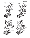
Bolt-On Cabinets—Matching battery cabinets are designed to bolt only onto the left side of the UPS
module cabinet. Use bolts that ship with each unit to connect cabinet frames at posts, two places in
the front and two places in the rear.
Service Clearance—Allow front access to the battery cabinet at all times for maintenance and
servicing. Electrical codes require that the battery cabinet be installed with no less than 3 feet (1m) of
clearance at the front of the cabinet when operating. Side and rear panels do not require service
clearance.
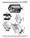
Cables—Cables may be run between the cabinets through cutouts in the top of the cabinet,
eliminating the need for external conduit runs. Route cables before moving cabinets into final position
for bolting together. No top or bottom entry cables are required, except for remotely located cabinets
which require conduits.
Software—To allow the UPS to accurately display the battery run time, the number of battery
cabinets must be noted when performing initial startup and setup using the configuration software.
This is to be performed by the Liebert Services engineer when commissioning the unit.
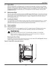
Casters and Adjustable Stops—The adjustable stops are not designed to bear the full weight of the
cabinet. Lower the stops until they are finger-tight in contact with the floor. Then tighten a small
amount with a wrench (less than two turns) to give a good friction fit. When mounting the battery
cabinet on seismic stands, ensure that the casters are bearing the weight of the cabinet.
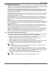
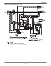
4.4.4 Connecting the Battery Cabinet to the UPS
After the battery cabinet equipment has been positioned and secured for operation and the batteries
have been connected, connect the power cables as described below (see Figure 23).
1. Verify that all incoming high and low voltage power circuits are de-energized and locked out or
tagged out before installing cables or making any electrical connections.
2. Remove the UPS right side panel to gain access to the ground and battery busbars.
3. Remove the battery cabinet front panel to gain access to the busbars.
4. Connect the safety ground and any necessary bonding ground cables to the copper ground busbar.
(example: UPS located on the bottom of the equipment below the power connections).
All cabinets in the UPS system must be connected to the user's ground connection.
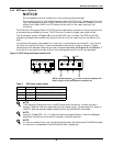
5. Connect the system battery cables from the UPS battery terminals (+ N -) to battery cabinet
breaker BCB (+ N -) as shown in Figure 23. Be sure that the battery connections are made with
the right polarity, and tighten the connections to 240lb-in. (27N-m) (M10 bolt). Do not close the
battery circuit breaker before the equipment has been commissioned.
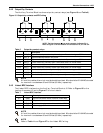
6. Connect TB1 from battery cabinet to J4 and J8 on the UPS according to Table 10.
NOTE
The grounding and neutral bonding arrangement must be in accordance with the National
Electrical Code and all applicable local codes.
NOTE
The shunt trip drive capability for the battery breaker is 220VDC at 2.4A.