


Chapter 1 Product Features
IPMC7126E/7616E I/O Module Installation and Use (6806800A45B)
9
Input/Output Modes
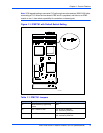
Both modules are designed to be plugged into PMC slot 1 of the base board. As stated earlier,
these SBCs have two P2 I/O modes (IPMC and PMC) that are user configurable. The user
should configure the baseboard for the IPMC module being used.
The jumpers route the on-board Ethernet port 2 to row C of connector P2. When used, both
modules are backwards compatible with the MVME761 rear transition module and P2 adapter
card (excluding PMC I/O routing) used on the MVME2600/2700. The rear panel Ethernet is not
available when using the IPMC712.
LEDs
Both modules use two LEDs to provide PMC status.
■ The module’s green SCSI LED is lit when the SCSI device is Master
■ The module’s green PIB LED is lit when the PCI bus grant to the PIB is asserted
PCI Signaling Voltage Level
Both modules will operate with only +5V signaling levels.
RS232 Interface
On the IPMC712 module, the four serial ports are used to communicate at RS232 voltage levels
(P14). The first three ports are fixed asynchronous ports, while the remaining port can be
configured as either a synchronous or an asynchronous port.
For additional handshaking signals, the IPMC712 module has the following features:
■ Port 1 has RTS and CTS
■ Ports 2, 3, and 4 have RTS, CTS, DTR, DCD
■ Port 4 has configurable serial clock signals RTxC and TRxC
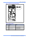
Jumpers J2, J3 and J5 determine the sources for these two signals, refer to Figure 1-5 on
page 7.