


IPMC7126E/7616E I/O Module Installation and Use (6806800A45B)
Chapter 3 Programming
16
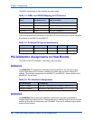
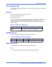
The General Purpose I/O (GPIO) pin assignments for the SCSI Controller are shown in the
table below. A 1x4 switch (S1) is provided to configure GPIO pins 2 and 3. The factory default
setting shall be for Ultra-Speed and Ultra-Wide SCSI.
SW1-P1 controls GPIO2 (Ultra/FAST SCSI) and SW1-P2 controls GPIO3 (Wide/Narrow SCSI
bus. SW1-P3 and SW1-P4 are No Connect. Select the SCSI characteristics of your
configuration according to the following table:
Table 3-1. GPIO Pin Assignments
GPIO Pin Direction Level Usage
GPIO1_MASTER_l
output 1 SCSI LED; SCSI is not MASTER.
0 SCSI is MASTER.
GPIO2
input 1 SCSI speed; selectable by switch S1.
S1:1 OFF selects Ultra
0 S1:1 ON selects FAST (default).
GPIO3
input 1 SCSI bus width; selectable by switch S1.
S1:2 in OFF selects Wide-SCSI.
0 S1:2 in ON selects Narrow-SCSI.
0, 4, 5, 6, 7, 8 - - Not used.
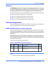
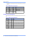
Table 3-2. SCSI Speed/Width Settings Using GPIO2:[1,2]
SCSI Type Width Speed
FAST SCSI Narrow (8 bit) 10MB/second
FAST SCSI Wide (16 bit) 20MB/second
Ultra SCSI Narrow (8 bit) 20MB/second
Ultra SCSI Narrow (16 bit) 40MB/second
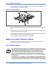
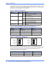
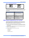
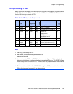
Figure 3-1. GPIO Switch Settings (S1)
Width of Bus Ultra (P1 OFF) Fast (P1 ON)
Wide (16-bit) SCSI bus (P2 OFF) 40MB/second 20MB/second
Narrow (8-bit) SCSI bus (P2 ON) 20MB/second 10MB/second
ON ON
1
1
88
S1-P3=1
S1-P4=1
S1-P2=1
S1-P1=1
S1-P3=0
S1-P4=0
S1-P2=0
S1-P1=0