Appendix B: NT5C10CO shelf 107
25A Switch Mode RectifierNT5C06B / C Installation and User Manual
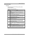
Power-up and verification
Verification
For systems equipped with the NT5C10CO power shelf, proceed as
indicated in Procedure 22.
Procedure 22 - Power-up and verification
Step Action
1
Verify that the AC circuit breakers of the rectifiers are in the “OFF”
position.
2
Release the clamping bar of the power shelf, by loosening the two
retaining screws.
3
Remove the right blank panel from the power shelf by removing the
retaining screw, pushing it up and pulling it out.
4
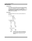
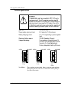
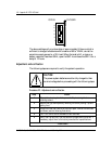
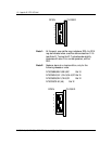
Locate the timer switch SW1 (located on the circuit pack at the right side
of the power shelf) and verify the settings. Default factory settings
should be as follows (24-hour delay):
5 Plug the AC power plug into the wall receptacle.
6 Turn “ON” the AC circuit breakers of the main rectifier. Verify that the
DELAYED START yellow LED is lit.
7 Verify the main rectifier voltage and set the voltage limits as specified by
the system and the manufacturer of the battery by referring to the
“Start-up procedure” section found in the “Installation and start-up
procedure” chapter of this manual.
8 The “Delayed Start” rectifier must be adjusted to the same voltages as
the main rectifier. To do so, turn OFF the main rectifier and turn “ON” the
AC breaker of the delayed rectifier. Repeat Step 6 & 7 on the unadjusted
rectifier.
9 Turn on the DC breaker of the main rectifier.
10 Wait until the delayed start yellow LED is extinguished (12h or 24h) OR
until the system batteries are fully charged to their nominal voltage
before proceeding to the next procedure: “Adjustment and verification”.
–end–


