73
25A Switch Mode RectifierNT5C06B / C Installation and User Manual
Maintenance
Maintenance
Rectifier
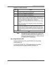
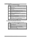
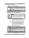
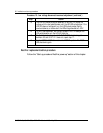
Procedure 20 - Float/equalize and remote equalize
Step Action
1 Disconnect the sense leads from the rectifier, by either disconnecting a
quick disconnect tab TB1 on the shelf or removing the appropriate
system fuse. (See the “Introduction” chapter for system applications.)
2 Open the output DC breaker. The unit is ready for local adjustment.
3 The unit should provide voltage to the front panel test point terminals. If
it does not, cycle the AC breaker to reset the unit.
4 Momentarily hold the FLT/EQL switch to EQL for local equalize.
5 Using a voltmeter, verify and adjust the EQL potentiometer to obtain an
output voltage reading of 0.5 volts (see Note below) above the system
equalize requirement.
6 Release the FLT/EQL switch. Verify that the output voltage drops to the
float value plus 0.5V (see Note below).
7 Verify the HVSD level. It is recommended that it be set approximately 3 V
above the shutdown limit of the power system. Refer to the “Installation
and start-up procedure” chapter, subsection “Start-up procedure”, for the
verification procedure.
8 Reconnect the sense leads locally to the rectifier. Close the output DC
breaker. Cycle the AC breaker to reset the unit. The RFA/ON LED should
be green.
–end–
Note:
The 0.5 volt DC extra does not apply to MPR25 rectifiers
above Release 30.


