


Surge Protective Devices
Installation, Operation and Maintenance Manual 8 Liebert SPDs SL-22075 Rev 0, 9/2010
All electrical connections should be installed by a qualified
(licensed) electrician only. All wiring must comply with the
National Electrical Code (NEC) and applicable local codes.
VERIFY THAT ALL POWER CIRCUITS ARE
DE-ENERGIZED AND LOCKED OUT BEFORE MAKING
ELECTRICAL CONNECTIONS.
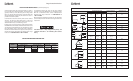
Voltage Ratings and Power Source Configurations —
Before making connections to the unit, verify that the unit
model number and nameplate voltage rating are appropriate
for connection to the intended power source. See the chart
on page 4 for voltage rating applications with typical power
source configurations.
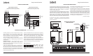
Wire Connections — With parallel connection, the size of the
wiring to the SPD unit is independent of the protected circuit’s
ampacity. NEC Article 285-21(B) requires surge suppressor
connecting conductors to be at least #14 copper or #12
aluminum. To reduce the wiring impedance to surge currents,
it is recommended that the phase, neutral (if required),
and ground conductors are twisted together and routed in
the same raceway (conduit). Avoid any sharp bends in the
conductors.
Overcurrent Protection — The SPD unit conducts practically
no current under normal operation and only conducts very
short duration transient surge currents.
NEC Considerations — The following is from the National
Electric Code 2008 Edition.
NEC 285.21 Connections
NEC 285.23 Type 1 SPDs. Shall be installed in accordance with
285.35(A) and (B).
(A) Installation. Type 1 SPDs shall be installed as follows:
(1) Type 1 SPDs shall be permitted to be connected to
the supply side of the service disconnect as permitted in
230.82(4) or
(2) Type 1 SPDs shall be permitted to be connected in
Type 2 locations as specified in 285.24.
(B) At the service. When installed at the services, the
grounding conductor of a Type 1 SPD shall be connected to
one of the following:
(1) Grounded service conductor
(2) Grounded electrode conductor
(3) Grounding electrode for service
(4)Equipment grounding terminal in the service equipment
Voltage Protection Ratings — To obtain the voltage
protection ratings (VPRs), as obtained by Underwriters
Laboratory, Incorporated, in accordance with the Standard
for Safety, Surge Protective Devices (SPDs), Standard 1449, Third
Edition, released (2009), marked on this product, the wire size
listed for each product must be utilized to connect the unit to
your facilities’ power grid. Connections made with conductors
other than the wire size listed may result in different VPRs.
Circuit Ampacity Limitations — Representative samples
of these products have been investigated by Underwriters
Laboratories, Incorporated to withstand, without exposing
live circuits or components at system voltages and fault
currents up to 200,000 AIC, as described in the Standard for
Safety, Surge Protective Devices (SPDs), Standard 1449, Third
Edition, released (2009).
System Grounding and Bonding — The performance and
safety of any SPD system is dependent on proper grounding
and bonding. Grounding is required for safety. Correct
implementation also enhances equipment performance.
Incorrect grounding can reduce or impede the SPD’s
operation.
All electrical circuits to the SPD must include an equipment-
grounding conductor as
required by the NEC and local
codes.
UNGROUNDED POWER SYSTEMS ARE INHERENTLY
UNSTABLE AND CAN PRODUCE EXCESSIVELY HIGH LINE-TO-
GROUND VOLTAGES DURING CERTAIN FAULT CONDITIONS.
DURING THESE FAULT CONDITIONS ANY ELECTRICAL
EQUIPMENT, INCLUDING AN SPD, MAY BE SUBJECTED TO
VOLTAGES WHICH EXCEED THEIR DESIGNED RATINGS. THIS
INFORMATION IS BEING PROVIDED TO THE USER SO THAT
AN INFORMED DECISION CAN BE MADE BEFORE INSTALLING
ANY ELECTRICAL EQUIPMENT ON AN UNGROUNDED
POWER SYSTEM. CONTACT FACTORY FOR UNGROUNDED
APPLICATIONS.
An insulated grounding conductor is required in addition to any
metallic raceway, which may be used as a grounding conductor.
For parallel-connected SPDs, the grounding conductor should
be the same wire size as the associated power conductors.
ELECTRICAL CONNECTIONS
Installation, Operation and Maintenance Manual 3 Liebert SPDs SL-22075 Rev 0, 9/2010
Surge Protective Devices
(continued on page 5)
MONITORING FEATURES
External Status Indicators (Standard) — These indicators
provide a summary of the status of the surge SPD module.
For normal conditions, the green “OK” LED is illuminated and
the red “Service” LED is extinguished. If the surge SPD module
requires replacement, the green “OK” LED is turned off and
the red “Service” LED illuminated.
Audible Alarm (Standard) — If the surge SPD module requires
replacement, an audible alarm is activated to draw attention
to the fact that repair service is required to restore the system
to normal operation. An audible alarm disable is provided to
silence the alarm. The system will automatically reset itself
after repair. The audible alarm switch and “Service” LED can be
tested by activating the “Test” switch on the system monitor
panel.
Summary Alarm Contact (Standard) — Two sets of summary
alarm Form C relay contacts (2 N.O. and 2 N.C.) are provided
for remote indication of the failed surge SPD module. Contacts
are rated 5 amps at 250 VAC maximum with a power factor of
1.0. Access to the contacts is provided via contact terminals
located on the printed circuit board mounted on the inside of
the unit’s cover.
Surge Counter (Optional) – The surge counter is provided for
transient voltage surge monitoring. The counter totalizes line
surges monitored since the last time the counter was reset.
The circuit counts all surges that deviate from the line sine
wave. The factory setting is 30% over nominal line voltage.
Other settings include 50%, 70%, and 100%.
TROUBLESHOOTING/ SERVICING/
MAINTENANCE
Troubleshooting
If status failure indication occurs or summary alarm contacts
has changed states, a qualified electrician shall first determine
if the systems voltage and proper phasing exists.
If the SPD remains in an alarm condition once the electrician
is satisfied that the electrical system and its connections are
normal, the unit should be repaired.
At this point consult the factory, having available the following
information:
• Unit identification number – (refers to the model and serial
numbers detailed on the data label and is located on the front
of the enclosure.)
• Nature of problem – (including status of all status indicators
and alarms).
Servicing
The Liebert SH Series comes with a ten year parts and five
year labor warranty (see Warranty Information). For servicing
assistance, contact your local Liebert Sales Representative or
Emerson Network Power, Surge Protection at 800-288-6169
or 607-721-8840.
ONLY QUALIFIED PERSONNEL SHOULD PERFORM
MAINTENANCE ON THE SYSTEM.
HAZARDOUS VOLTAGES ARE PRESENT INSIDE THE UNIT
DURING NORMAL OPERATIONS.
ELECTRICAL SAFETY PRE-CAUTIONS MUST BE FOLLOWED
WHEN SERVICING THIS UNIT.
TO PREVENT RISK OF ELECTRICAL SHOCK, TURN OFF AND
LOCK OUT ALL POWER SOURCES TO THE UNIT BEFORE
SERVICING UNIT.
Corrective Maintenance - The Liebert SPD is designed for
years of trouble-free operation. However, even the most
reliable equipment may fail under abnormal conditions.
Diagnostic indicators are provided to indicate when the unit
needs repair or replacement. To ensure continuity of surge
protection, failed units should be repaired or replaced at the
earliest convenient service opportunity. When replacing surge
modules, other components should be inspected for damage
and replaced if necessary. Standard electrical troubleshooting
procedures should be used to isolate problems other than failed
surge current diverter modules. When replacing components,
for continued proper operation and safety, replace only with
identically rated components. Please contact factory for
information on replacement parts.
Preventative Maintenance (Inspection and Cleaning) -
Periodic system inspections, cleaning, and connection checks
are recommended to ensure reliable system performance and
continued surge transient protection.
It is difficult to establish a schedule for preventative
maintenance since conditions vary from site to site. Inspections
for failed surge modules using available diagnostics should be
done routinely (weekly or monthly).