


Installation, Operation and Maintenance Manual 5 Liebert SPDs SL-22075 Rev 0, 9/2010
Surge Protective Devices
Dimensional Information
Liebert SH Series
E
F
(4X)
B
A
D
C
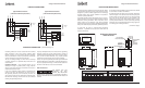
Service Panel for
Loads to be Protected
Phase L1/A
Phase L2/B
Phase L3/C
Disconnect/Main
Breaker for
Panel
Neutral Buss
Ground Buss
Dedicated
Disconnect
(Optional)
Recommended Wire
Entrance
Summary Alarm Contacts (X2)
Pin 1 = Normally Open
Pin 2 = Common
Pin 3 = Normally Closed
TB1 TB2
1 2 3 1 2 3
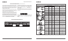
Liebert SH Series (Without Disconnect)
Model
#
Dimensions (Inches)
Weight
(lbs)
A B C D E F
SH025
SH032
SH040
SH075
16
16
16
20
8
8
8
8
17.25
17.25
17.25
21.25
9.5
10
10
14
0.44
0.44
0.44
0.44
35
49
49
85
16
16
16
20
Liebert SH Series (With Disconnect)
Model
#
Dimensions (Inches)
Weight
(lbs)
A B C D E F
SH025
SH032
SH040
SH075
16
16
16
24
8
8
8
8
21.25
21.25
21.25
21.25
10
10
10
18
0.44
0.44
0.44
0.44
45
58
58
95
20
20
20
20
Installation, Operation and Maintenance Manual 6 Liebert SPDs SL-22075 Rev 0, 9/2010
Surge Protective Devices
The Liebert SH Series Hybrid Surge Protective Devices (SPDs)
are high quality, high energy surge current diversion systems
designed to protect sensitive equipment from damaging
transient voltage surges. Proper installation is required for
maximum system performance.
The installer should perform the following steps to assure a
quality installation. The entire installation manual should be
read before starting installation. These instructions do not
replace national or local electrical codes. Check applicable
electrical codes to ensure compliance. Installation of the Liebert
SPD system should only be performed by qualified personnel.
1. Insure that all power is removed before beginning
installation. A qualified licensed electrician shall install all
electrical connections.
2. The SPD is provided in NEMA 4 enclosures which are suitable
for use in indoor or outdoor installations.
3. Determine where the SPD is to be mounted, allowing for
minimum length of wire between itself and the input power
terminals of the service panel. Punch or cut the proper hole
size in the side of the SPD closest to the knockout to be
utilized in the service panel. Drill mounting holes in wall at
location picked for SPD next to service panel using mounting
dimensions shown in the table below. Mount surge suppressor
to wall using 3/8” mounting hardware.
Grounding conductors must be routed with the associated
power conductors in the same raceway (conduit). When
metallic raceways are used, adequate electrical continuity
must be maintained at all raceway connections, particularly
raceway terminations to the electrical enclosures.
The use of isolating bushings or other means to interrupt
a metallic conduit run is a potential safety hazard and is not
recommended.
Grounding Electrode — Surge protective devices do not
discharge all surges to ground (earth). Surge protective
devices can also divert the surge current back to its source to
complete the electrical circuit.
In the case of lightning whose potential is developed with
respect to the earth, the SPD diverts the surge current to
the grounding electrode (earth connection). However, for
most transient surges that are developed by switching loads,
the SPD diverts the surge current back to its source without
involving the grounding electrode.
For proper SPD performance, the service entrance grounding
electrode system must comply with the NEC by having all
available electrodes (building steel, metal water pipe, driven
rods, concrete encased electrodes, etc.) properly bonded
together and connected to the power system grounding.
The use of a separate grounding electrode to ground the SPD
defeats the effectiveness of the SPD, is a potential safety hazard,
may cause equipment damage, is an NEC violation (reference
NEC 250-51 and 250-54), and is not recommended.
Neutral Connection –
FOR PROPER AND SAFE
OPERATION, THE SPD’s
NEUTRAL, MUST BE RELIABLY
CONNECTED TO THE NEUTRAL OF THE SOURCE. FAILURE TO
PROVIDE A RELIABLE NEUTRAL CONNECTION MAY RESULT IN
FAILURE!
(continued from page 3)
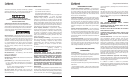
Typical Parallel Connections
(without Internal Rotary Disconnect)
Typical Parallel Connections
(with Internal Rotary Disconnect)
To
Protected
Loads
Liebert
Surge
Protective
Device
Protected
Panel
Wire should be
less than 5 feet
and straight
as possible
Neutral
Phase(s)
Transient
Ground
Safety
Ground
Neutral
Phases
Ground
To
Protected
Loads
Liebert
Surge
Protective
Device
Protected
Panel
Wire should be
less than 5 feet
and straight
as possible
Neutral
Phase(s)
Transient
Ground
Safety
Ground
Neutral
Phases
Ground
Rotary
Disconnect
To
Protected
Loads
Liebert
Surge
Protective
Device
Protected
Panel
Wire should be
less than 5 feet
and straight
as possible
Neutral
Phase(s)
Transient
Ground
Safety
Ground
Neutral
Phases
Ground
To
Protected
Loads
Liebert
Surge
Protective
Device
Protected
Panel
Wire should be
less than 5 feet
and straight
as possible
Neutral
Phase(s)
Transient
Ground
Safety
Ground
Neutral
Phases
Ground
Rotary
Disconnect
ELECTRICAL CONNECTIONS
INSTALLATION INSTRUCTIONS
PARALLEL CONNECTIONS
(continued on page 7)