


Installation, Operation and Maintenance Manual 7 Liebert SPDs SL-22075 Rev 0, 9/2010
Surge Protective Devices
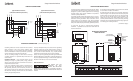
Source Configurations
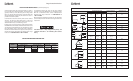
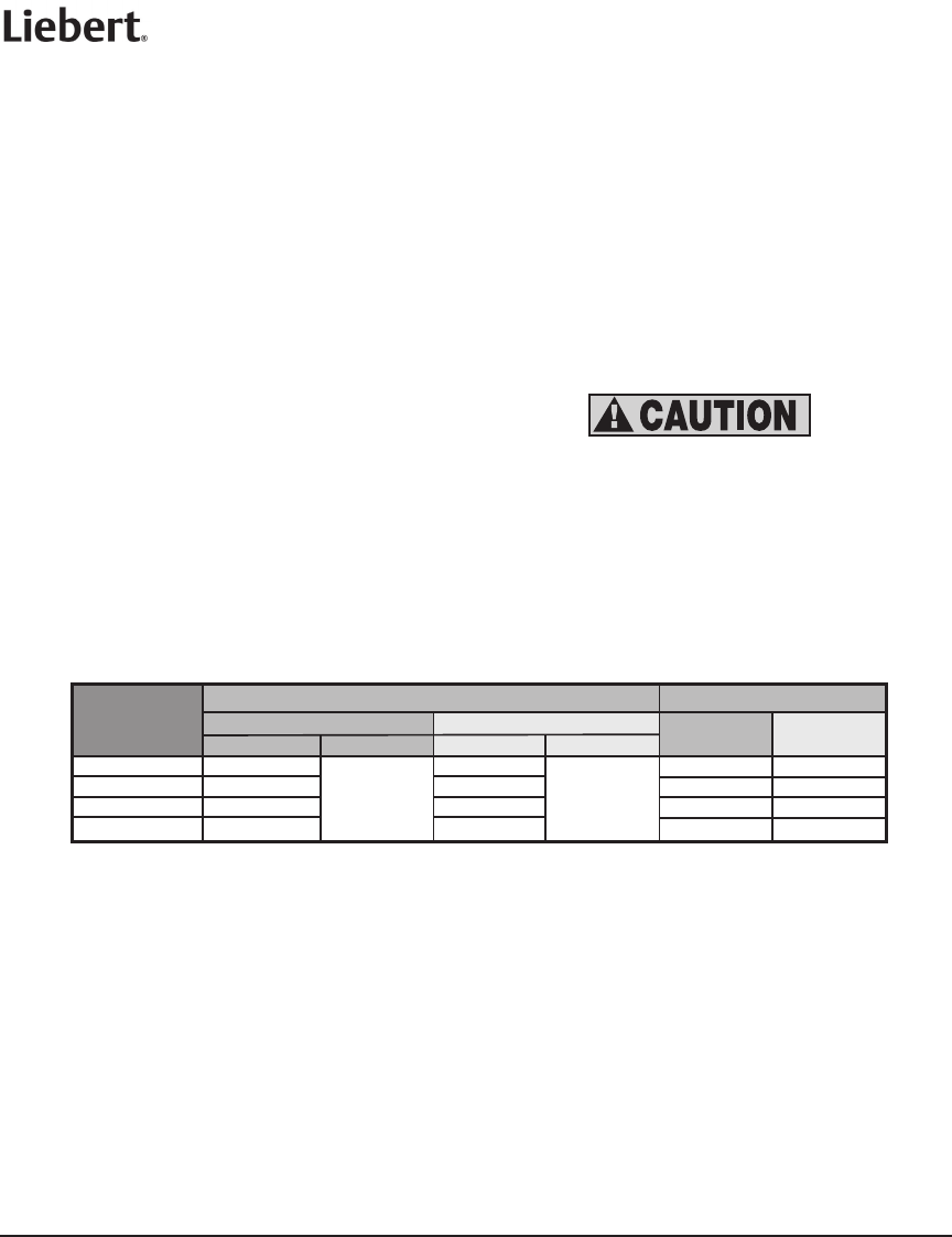
VOLTAGE RATINGS AND POWER SOURCE CONFIGURATIONS
Nominal Operating Voltage
L-N L-G L-L
Maximum Continuous
Operating Voltage
Model Voltage Code
(Found in part number)
Single Phase L-N, 2 W + G
Single Phase L-L, 2 W + G
Single Phase, 3 W + G
Three Phase Delta, 3 W + G
Three Phase Wye, 4 W + G
Three Phase Wye, 3 W + G No Neutral
150 L-N
320 L-N
320 L-N
120 N
230 N
277 N
320 L-L
580 L-L
580 L-L
240D
400D
480D
N/A 240 240
N/A 380-415 380-415
N/A 480 480
320 L-N
240S
240, 277 240, 277 480
300 L-L
320 L-L
580 L-L
580 L-L
208L
240L
400L
480L
N/A 208 208
N/A 240 240
N/A 400 400
N/A 480 480
Note 1: For other voltages or source configurations, consult factory.
150 L-N
320 L-N
320 L-N
120Y
230Y
277Y
120 120 208
220-240 220-240 380-415
277 277 480
150 L-G
320 L-G
320 L-G
120X
230X
277X
N/A 120 208
N/A 220-240 380-415
N/A 277 480
L
N
G
L
N
G
L1
L2
G
L1
L2
G
L1
N
G
L2
L1
N
G
L2
A
B
C
GG
B
A
G
N
C
A
N
B
C
G
A
B
C
G
L
N
G
L
N
G
L1
L2
G
L1
L2
G
L1
N
G
L2
L1
N
G
L2
A
B
C
GG
B
A
G
N
C
A
N
B
C
G
A
B
C
G
L
N
G
L
N
G
L1
L2
G
L1
L2
G
L1
N
G
L2
L1
N
G
L2
A
B
C
GG
B
A
G
N
C
A
N
B
C
G
A
B
C
G
L
N
G
L
N
G
L1
L2
G
L1
L2
G
L1
N
G
L2
L1
N
G
L2
A
B
C
GG
B
A
G
N
C
A
N
B
C
G
A
B
C
G
L
N
G
L
N
G
L1
L2
G
L1
L2
G
L1
N
G
L2
L1
N
G
L2
A
B
C
GG
B
A
G
N
C
A
N
B
C
G
A
B
C
G
L
N
G
L
N
G
L1
L2
G
L1
L2
G
L1
N
G
L2
L1
N
G
L2
A
B
C
GG
B
A
G
N
C
A
N
B
C
G
A
B
C
G
120 120 208, 240
N/A 208 208
300 L-L 208D
150 L-N
120S
Installation, Operation and Maintenance Manual 4 Liebert SPDs SL-22075 Rev 0, 9/2010
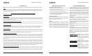
4. Connect black wires (line or phase) marked L1/A, L2/B or
L3/C, the white wire (neutral) marked N, and the green wire
(ground) marked G, of the SPD using the wire range listed
below. To yield the best performance of the SPD within the
electrical distribution system, keep all conductors as short as
possible and avoid sharp bends.
5. Connection to the unit’s summary alarm contacts shall be
with #18 – 22 AWG. The ratings of the Form ‘C’ contacts are
5 amps at 250 VAC maximum with a power factor of 1.0. For
additional information, see “Monitoring” section.
6. Apply power. The surge protector is fully operational when
the GREEN LEDs on the modules and the front door of enclosure
are illuminated. If the GREEN LEDs are extinguished or a RED
LED is illuminated, check to ensure that power is applied to
the SPD. If an abnormal indication is present, remove power to
the SPD and contact Liebert/Emerson Network Power Surge
Protection at 1-800-288-6169 or 1-607-721-8840.
7. Periodically monitor the status of the LEDs. Reduced
protection exists if the GREEN LEDs are extinguished or the
RED LED is illuminated. Please contact Liebert/Emerson
Network Power Surge Protection at 1-800-288-6169 or
1-607-721-8840.
8. The protection modules in these SPDs may be replaceable,
contact Liebert/Emerson Network Power Surge Protection for
replacement.
If the SPD model is a Wye configured unit (4W+G), and
a Neutral connection is not available, please contact
factory.
Model #
Allowable Range
Factory Suggested Size
Circuit Breaker Size
Connection Wire Size
Circuit Breaker
Size
Connection
Wire Size
With Disconnect Without Disconnect With Disconnect Without Disconnect
SH025
SH032
SH040
SH075
15A – 150A
15A – 175 A
15A – 175A
15A – 175A
15A – 175A
#8 – 1/O AWG
#8 – 1/O AWG
#8 – 1/O AWG
#8 – 1/O AWG
60 Amp
80 Amp
80 Amp
100 Amp
#6 AWG
#4 AWG
#4 AWG
#2 AWG
#14 – 2/O AWG
SUGGESTED BREAKER AND WIRE SIZE
INSTALLATION INSTRUCTIONS
(continued from page 6)
120 120 N/A
230 230 N/A
277 277 N/A