


Page 12
MSL600
Installation, Operation & Maintenance Manual
IP262/Z0, Rev. AB
February 2012
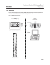
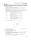
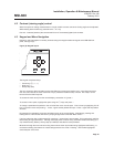
With the bracket on the ground adjust the pivot tube up or down the main support tube until the distance between
the angle bracket and midpoint of the transducer is dimension A. Adjust the clamping bracket up or down the
main support tube to dimension B so it will be just clear of the final clamping position.
If the clamp is higher than the pivot tube this will need to be removed and reassembled in reverse order (view X).
If dimension A is too large and cannot be achieved, remove the pivot tube assembly, screw on the extension tube
and refit the pivot tube (view Y). If the pivot arm is to be set at an angle or set to the opposite hand, this should
be done at this stage.
Adjust the transducer guard so that it is at 90° to the pivot arm, projecting under the pivot arm and approximately
25mm (1 inch) below the bottom of the transducer.
If necessary move the chain attachment clamps to positions convenient for swinging the transducer out of the
water. Adjust the chain so that it is slightly slack with the unit fully extended and any excess chain is hanging on
the main support tube and not the transducer arm.
The cable and air hose can now be attached to the bottom of the main support tube with the cable ties provided.
The cable and hose must make a 360° loop between transducer tube and main support tube to allow for flexing
when the arm is lifted. Move the transducer arm up and down and check that the cable and hose move freely
without excessive strain.
Before installing the unit on the bridge check that all the fittings associated with pivot tube are securely tightened,
including those which have not been adjusted, as these are often difficult to reach later.
3.3.2 Installing the bracket on the bridge
Before carrying the unit on to the bridge, swing the transducer arm into the up position and attach it to the main
support tube with the chain. This makes the unit more compact and easier to manage. Lift the unit over the
handrail and hook it on to the horizontal centre tube of the rail. Release the rail clamp and push it up firmly under
the rail. While pushing on the barrel of the rail clamp (not the lug) retighten the clamping screw. This will
ensure a tight fit against the rail.
Loosen the clamping bracket assembly, attach it to the kicking board or similar structure and retighten. The
studding allows the main support tube to be adjusted approximately to the vertical position. In some instances
one or both nuts between the clamps will need to be removed. Tighten all fixings.
Lower the transducer arm carefully into the water and check the water surface is approximately in line with the top
of the parallel portion of the transducer and it is clear of obstructions. Adjust the pivot arm height and angle as
necessary. It is recommended the unit be removed from the bridge to make these fine adjustments. Ensure the
cable and air hose still move freely without excessive strain when the transducer is raised and lowered.
Check that the transducer arm is hanging vertically. The transducer guard also functions as a balance arm.
To adjust, swing the arm up and loosen the transducer guard. Move the guard backwards or forwards as
appropriate and retighten. Repeat until the arm hangs vertically.
When the unit is installed and functioning correctly check all fittings are securely tightened, including those which
have not been adjusted.
3.3.3 Attaching the MSL600
The MSL600 and compressor box come attached to a back plate complete with mounting lug. Check the
clamping screw of the mounting lug is clear of the inside face and slide the complete unit onto the top of the main
support tube. Orientate the unit to the correct position and tighten the clamping screw.
Run the cable and hose up to the control unit avoiding sharp bends and flattening of the hose. Plug the air hose
onto the air connector on the bottom of the compressor box. The unit is now ready for wiring.
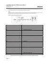
Additional fittings for MSL bracket (UK only) can be obtained from:
Alvin Products Limited, Knight Works, 10-12 Hampton Street, London, SE1 6SN
Tel. 020 7708 2004, Fax. 020 7708 3044, Web site:
www.alvin.net
Fittings are ALVIN ‘KEY’ CLAMPS (Size 5 - 26.9mm dia.) Similar fittings are also available from other manufacturers.
Note: Socket head screws require 1/4” A/F Hex key clamp bracket screws require 17mm A/F spanner.