


Version 1.02
4
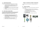
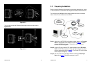
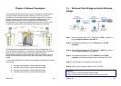
2.2 Locate the Wireless client bridge and Inline
Power Injector Ports
Interface on the Wireless client bridge Unit
9 Ethernet Port 1 for connecting the RJ-45 CAT-5 Ethernet
cable.
9 RS-232 Console Port 2 for connecting the 1.8m RS-232 null
modem console cable.
NOTE: The RJ-45 Ethernet cable is not provided in Wireless client bridge
shipping package as an accessory. User can find one from
computer store in accordance with the length required for outdoor
deployment.
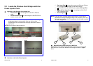
NOTE: How to make up Water protect kit
PS:1.Red line is RJ-45 cable
2.Use dryer blew Ardent shrink casing pipe
Before After
Interface on the Inline Power Injector
Version 1.02
5
9 Data Input Port 3 for connecting cross-over Ethernet Cable to
PC or straight Ethernet cable to Hub Switch Router.
9 110~240VAC, 50~60Hz AC/DC power adapter DC Input Port
4
9 Power & Data Output Port 5 for connecting the 30m RJ-45
CAT-5 Ethernet Cable.
9 Grounding Port 6.
NOTE: The cross-over or straight type Ethernet cable is not provided in
Wireless client bridge shipping package as an accessory. User can
find one from computer store in accordance with the length required
for indoor deployment.
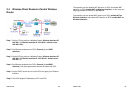
Mount Wireless client bridge on A Wall/Pole
The Wireless client bridge can be mounted on the wall, you can use the
Wall Mount kit to mount the Wireless client bridge as shown in Figure
2.2.1.
3
1
2
6
5
4