


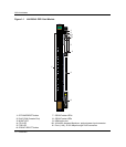

DFE-Gold Module
Matrix DFE-Gold Series PoE Module Hardware Installation Guide 1-3
TheDFE moduleportscanbeconfiguredtoprovideahighlevelofsecurity,controltraffic
bylimitingtherateoftrafficacceptedintothemoduleandprioritizingtraffictoexpedite
theflowofhigherprioritytrafficthroughthe module.Foracompletelistofcapabilities,
andinformationconcerninghowtoconfigure
theDFE modulefeaturesareprovidedin
theEnterasysMatrixDFE‐GoldSeriesConfigurationGuide.
TheDFE modulereceivespowerandbackplaneconnectivitywhenitisinsertedintothe
Matrix E7,Matrix N7,Matrix N5,orMatrix N3chassis.Thepowertosupportthe
DFE moduleconnectionsto802.3afPoE‐compliant48VdcPDs(powereddevices)can
be
fromthebackplaneofaMatrix N5chassisorfromanoptionalexternalMatrixN‐POE
PowerSystem.
TheMatrixN‐POEPowerSystemcanprovide48Vdctosupportuptoeight
PoE‐compliantDFE modules.TheconnectionfromtheN‐POEPowerSystemisbywayof
the48Vdc
~20AMaximumOptionalPowerInputconnectoronthefrontpanelofthe
DFE module.
Caution: Regardless of which chassis is used, the chassis system must be dedicated to
DFE-Gold modules (4xxxxx) only. Do not insert 7xxxxx modules or other legacy modules
into the same chassis with 4xxxxx modules as this will render the chassis inoperable.
Precaución: Cualquiera que sea el chasis que utilice, recuerde que el sistema debe
aplicarse exclusivamente a los módulos DFE (Distributed Forwarding Engine) de la serie
Gold (4xxxxx). No inserte módulos 7xxxxx ni otros módulos legado dentro de un chasis
con módulos 4xxxxx. Si lo hace, el chasis no funcionará.
Note: Only an N-POE Power System can be connected to the 48 Vdc ~ 20 A Maximum
Optional Power Input connector of a series PoE-compliant
DFE module such as the
4H4285-49.