


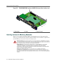


Gaining Access to Memory Modules
B-8 Mode Switch Settings and Option Installations
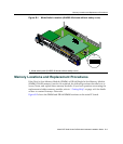
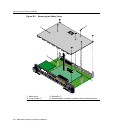
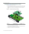
2. RemovethetwoscrewsfasteningtheNEMtotheDFE‐Gold modulefrontpaneland
removethestandofffasteningtheNEMtothemainboard.Savethetwoscrewsand
standoffforlaterusetoreinstalltheNEM.
3. LiftandremovetheNEMoffthetwomainPCboardconnectors.Nowyou
have
accesstotheDRAMSIMM.ToreplacetheDRAMSIMM,proceedto“Removingthe
DRAMSIMM”.
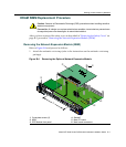
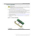
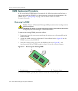
Removing the DRAM SIMM
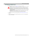
ToremovetheDRAMSIMM,refertoFigure B‐5andproceedasfollows.
1. RefertoFigure B‐5.PushtheconnectorarmsawayfromtheDRAMSIMMtoreleaseit
fromtheconnector.
2. RemovetheDRAMSIMMfromtheconnector.
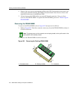
Figure B-5 Removing the Existing DRAM SIMM
Note: The ejector arms on this connector are not spring-loaded, so they will remain in the
open position until manually closed.
1 Connector arms 2 Memory module 3 Connector
Â
À
À
Á