


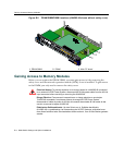
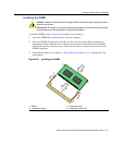
Gaining Access to Memory Modules
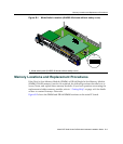
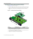
B-6 Mode Switch Settings and Option Installations
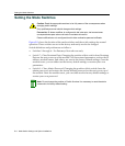
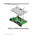
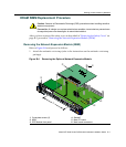
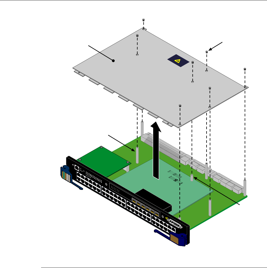
Figure B-3 Removing the Safety Cover
1 Safety cover 3 Standoffs (7)
2 Cover screws (7) 4 Standoff/spacer screwed to standoff under the interface board
1X
G
R
O
U
P
1
G
R
O
U
P
2
11X
13X
23X
OFFLINE/
RESET
COM
CPU
M
G
M
T
GR
OUP
SELECT
GR
OUP
1
2
3
4
5
6
7
8
9
10
11
12
POE
12
X
14X
24X
G
R
O
U
P
3
25X
35X
26X
36X
G
R
O
U
P
4
37X
47X
38X
48X
1
2
3
4
48V --- 20A MAX
OPTIONAL
PO
WER INPUT
4
H4
2
8
5
-
4
9
F
AST ENET
DFE
1
2
3
4
5
6
1
2
3
4
5
6
7G-6MGBIC-A
Á
À
Â
Ã