


EPSON Perfection 3200 Series
2 - EPSON Perfection 3200 Series 11/02
Electrical
Input voltage 100-120 VAC
range
Rated input 0.45 A
current
Power Approx. 24 W operating
consumption approx. 19 W in stand-by mode
approx. 5.5 W in power saving mode
Note: Scanners sold outside the US market may operate at a different
voltage. Check the label on the back of the scanner for voltage
information.
Environmental
Temperature Operation: 41 to 95 °F (5 to 35 °C)
Storage: –13 to 140 °F (–25 to 60 °C)
Humidity Operation: 10% to 80%
(without Storage: 10% to 85%
condensation)
Operating Ordinary office or home conditions; avoid
conditions extreme dust, direct sunlight, and strong
light sources.
Safety Approvals
Safety UL 1950
CSA C22.2 No. 950
EMC FCC part 15 subpart B class B
CSA C108.8 class B
USB Interface
Interface type Universal Serial Bus Specification
Revision 2.0
Connector type One receptacle (Type B)
Electrical Full Speed mode (12 Mbps) and High
standard Speed mode (480 Mbps), Universal
Serial Bus Specification Revision 2.0
Connector pin arrangement
FireWire Interface
Interface type IEEE 1394a-2000 compatible
Data transfer Half-duplex data / strobe differential
serial
Transfer speed Average: 4 Mbytes/sec
Peak: 50 Mbytes/sec
(100 to 400 Mbps)
Synchronization Clock synchronization with DS-Link
Encoding/ DS-Link
Decoding
Logic level 3.3. V
Connector pin arrangement
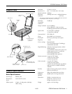
Transparency Unit
The transparency unit is built into the scanner lid.
Electrical Supply voltage: DC 21.6 to 26.4 V
Rated current: 0.5 A
Document Positive or negative film in the following
specifications sizes:
35 mm strips
35 mm slides
120/220 (6 × 9-cm) film
4 × 5-inch film
Readable area 4 × 9 inches (102 × 230 mm)
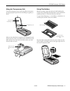
Scanning Transparencies and Film
Before scanning transparent documents, you need to remove
the scanner’s reflective document mat; this exposes the scanner’s
transparency unit (light source), which is built into the lid.
If you’re scanning slides or film strips, you’ll also need to use
one of the film holders.
Pin number Signal Connector
1VCC
2 –DATA
3+DATA
4 GND
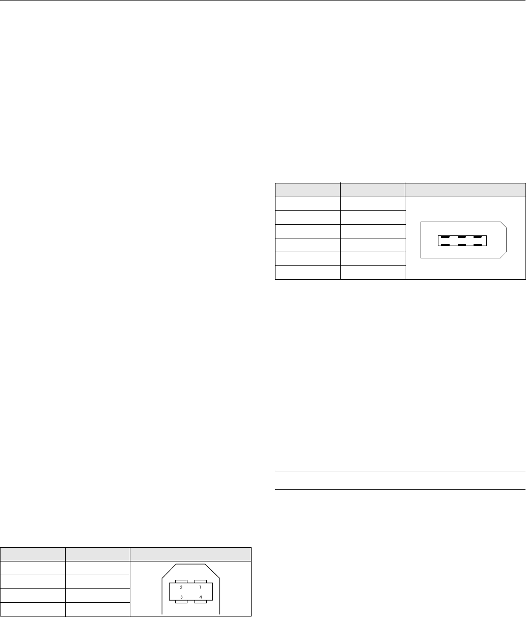
Pin number Signal Connector
1VCC
2GND
3 TPB–
4 TPB+
5 TPA–
6 TPA+
1
3
5
64
2