


EPSON Stylus Photo 700/EX Service Manual
Chapter 2 Operating Principles
Rev. A
2-
2
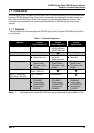
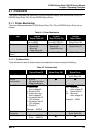
2.1.2 Electrical Circuit
The difference in electrical circuits for EPSON Stylus Photo 700 / EX and EPSON Stylus Photo
are as follows:
Table 2-3. Electrical Circuits
Item EPSON
Stylus Photo EX
EPSON
Stylus Photo 700
EPSON
Stylus Photo
Main Board C231MAIN
(Circuitry is the same
with C209MAIN for
EPSON Stylus Photo)
C233MAIN C209MAIN
Power Supply Unit C206PSB/PSE
Õ Õ
Control Panel C206PNL
(Same with EPSON
Stylus Color 400/600)
C209PNL
Õ
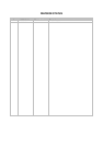
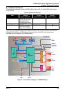
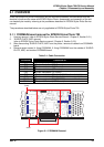
The circuitry of C233MAIN Board for EPSON Stylus Photo 700 is partly modified compared with
C209MAIN/C231MAIN for EPSON Stylus Photo and Stylus Photo EX, and a figure below
illustrates the circuit diagram of C233MAIN board.
IC 2
ASIC
(E05B55YA)
IC 1
CPU
(TM P95C061)
IC 5
DRAM(4M)
IC 3
PROM
IC 6
MROM
IC 1 4
UD N 2917
IC 1 5
UD N 2917
IC 1 6
Serial Transceiver
(SN75LBC775)
IC 1 1
EEPROM
(AT93C46)
IC 1 0
TIMER
(S-3510ANF)
CN3
PANEL
C N 4 /5 /1 1
PE Sensor
HP Sensor
ASF Sensor
CN6
CR Motor
CN7
PF Motor
CN8
HEAD
CN1
P a ra lle l
CN2
Serial
Data Bus (16bit)
Address B us
Nozzle Select Data
BAT1
IC 7
H8D 2813
VH
+42V
C 233M A IN
CN9
HEAD
Figure 2-1. Circuit Block Diagram - C233MAIN Board