


EPSON Stylus Photo 700/EX Service Manual
Chapter 3 Disassembly and Assembly
Rev. A
3-1
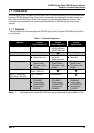
3.1 OVERVIEW
Since the structure of printer mechanism and the connection between the mechanism and the
electrical circuits are the same with EPSON Stylus Photo, disassembly and assembly of the unit
can basically be made by referring to the procedures described in EPSON Stylus Photo Service
manual.
The procedures described below are only applicable to EPSON Stylus Photo 700.
3.1.1 C233MAIN board removal for EPSON Stylus Photo 700
1. Housing removal. (refer to EPSON Stylus Photo Service manual / Chapter 3, Section 3.2.1)
2. “SHIELD PLATE, M/B” removal.
(refer to EPSON Stylus Photo Service manual / Chapter 3, Section 3.2.2)
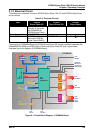
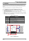
3. After dismounting “SHIELD PLATE, M/B” from the printer, remove all cables from C233MAIN
board.
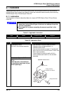
4. Remove seven screws (4: fixing C233MAIN, 3: fixing C233MAIN from the outside of “SHIELD
PLATE, M/B”) and remove C233MAIN board.
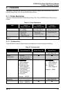
Table 3-1. Cable Connection
Connector Connected to
CN3
Ö
Control panel (C209PNL)
CN4
Ö
Printer mechanism (PE Sensor)
CN5
Ö
Printer mechanism (HP Sensor)
CN6
Ö
Printer mechanism (CR motor)
CN7
Ö
Printer mechanism (PF motor)
CN8
Ö
Printer mechanism (Printhead: VH, Nozzle select data)
CN9
Ö
Printer mechanism (Printhead: Nozzle drive signals)
CN10
Ö
Power supply unit (C206PSB/PSE)
CN11
Ö
Printer mechanism (ASF Sensor)
Screw
Screw
Figure 3-1. C233MAIN Removal