


EPSON Stylus Photo 700/EX Service Manual
Appendix
Rev. A
A-1
A.1 OVERVIEW
Since the electrical circuit (Main board and power supply unit) of EPSON Stylus Photo EX is the
same with EPSON Stylus Photo, this section only describes the main board: C233MAIN for
EPSON Stylus Photo 700.
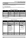
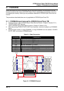
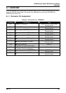
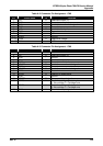
A.1.1 Connector Pin Assignment
Table A-1. Connector List - C233MAIN
Connector Connected to Table
CN1 Parallel I/F Connector Refer to EPSON Stylus Photo
Service manual
CN2 Serial I/F Connector Refer to EPSON Stylus Photo
Service manual
CN3
Ö
Control panel (C209PNL)
Refer to EPSON Stylus Photo
Service manual
CN4
Ö
Printer mechanism (PE Sensor)
Refer to EPSON Stylus Photo
Service manual
CN5
Ö
Printer mechanism (HP Sensor)
Refer to EPSON Stylus Photo
Service manual
CN6
Ö
Printer mechanism (CR motor)
Refer to EPSON Stylus Photo
Service manual
CN7
Ö
Printer mechanism (PF motor)
Refer to EPSON Stylus Photo
Service manual
CN8
Ö
Printer mechanism
(Printhead: VH, Nozzle select data)
Table A-2
CN9
Ö
Printer mechanism
(Printhead: Nozzle drive signals)
Table A-3
CN10
Ö
Power supply unit (C206PSB/PSE)
Refer to EPSON Stylus Photo
Service manual
CN11
Ö
Printer mechanism (ASF Sensor)
Refer to EPSON Stylus Photo
Service manual