


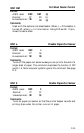

Interface
The PIC uses an &bit, Centronics
®
-compatible, parallel interface.
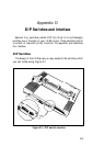
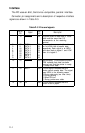
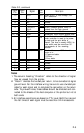
Connector pin assignments and a description of respective interface
signals are shown in Table D-3.
1
2
3
4
5
6
7
8
9
10
11
12
Return
Direc.
Pin
Signal
tion
Description
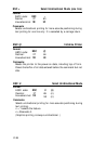
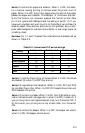
19
STROBE
IN
STROBE pulse to read data in. Pulse
20
21
22
23
24
25
26
27
28
DATA 1
DATA 2
DATA 3
DATA 4
DATA 5
DATA 6
DATA 7
29
30
DATA 8
ACKNLG
BUSY
PE
width must be more than 0.5
microseconds at the receiving
terminal.
IN
These signals represent information of
IN
IN
the 1st to 8th bits of parallel data,
respectively Each signal is at HIGH
IN
level when data is logical 1 and LOW
IN
when it is logical 0.
IN
IN
OUT Approximately 12-microsecond pulse.
LOW indicates that data has been
received and that the printer is ready
to accept more data.
OUT A HIGH signal indicates that the
printer cannot receive data. The signal
goes HIGH in the following cases:
1) During data entry (ea. char. time)
2) During printing
3) When Off-Line
4) During printer-error state
OUT A HIGH signal indicates that the
printer is out of paper.
Table D-3. Pins and signals
D-4