


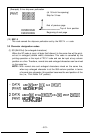
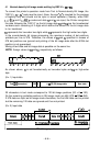
4.3 Relationship between data and dot wires
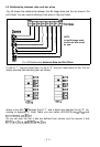
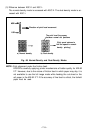
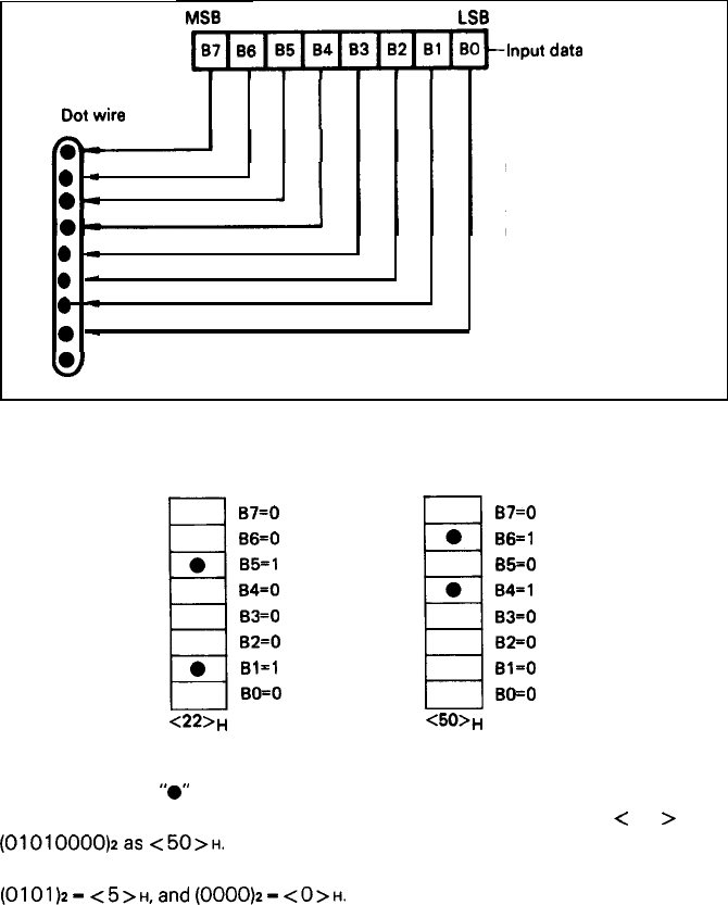
Fig. 63 shows the relationship between the Bit Image data and the dot wires in the
print head. You can control arbitrary 8 dot wires in the print head.
LSB
Input
data
Dot
wire
l
-
NOTE:
04
In the Bit Image mode,
the 9th dot wire cannot
be used.
l
-
0
.-
l
-
0
-
&
Fin. 63 Relationship between Data and Dot Wires
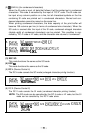
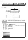
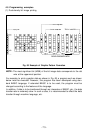
If a bit is “1“, the print head fires. If a bit is “0”, the print head does not fire. For ex-
ample, assume that data are given as follows;
B7=0
B6=0
B5=1
B4=0
B3=0
B2=0
Bl-1
BO=O
<22>,,
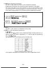
67=0
B6=1
B5=0
B4=1
B3=0
B2=0
Bl-0
BO=O
<50>,,
where a box with
“0”
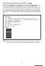
denotes the bit “1” and a blank box denotes the bit “0”. Ac-
cording to Appendix 4, Code Table, you can define (00100010)2 as
<
22
>
H and
(01010000)2as
<50>H.
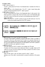
As you can see the first 4 bits are defined from column and the second 4 bits
(0101)2-
<5>H,and
(0000)2-
<O>H.
-71-