


APPENDIX S5U1C330MXD1 BOARD
EPSON S1C33 FAMILY DEBUG MONITOR
OPERATION MANUAL
16
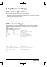
A.3 Connecting the System
Note:When connecting and disconnecting the system, make sure to turn off the power of the
S5U1C33xxxDx/ target board and the personal computer.
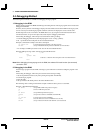
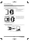
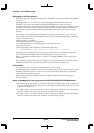
Connecting to the S5U1C33xxxDx board/user target board
S5U1C33xxxDx/target board I/F connector
S5U1C330MxD1 I/F connector
S5U1C33xxxDx
Figure A.3.1 Connecting to the S5U1C33xxxDx board
The S5U1C33xxxDx board has a connector used
for connecting with the S5U1C330MxD1.
Connect the S5U1C330MxD1 to the
S5U1C33xxxDx board with the
S5U1C33xxxDx/target board I/F connector.
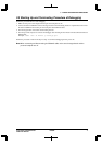
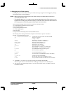
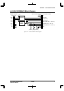
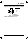
S5U1C33xxxDx/target board I/F connector
S5U1C330MxD1 I/F connector
(supplied with the S5U1C330MxD1 package)
S1C33xxx
User target board
SINx
SOUTx
SCLKx
#RESET
#NMI
(K63)
V
SS
V
CC
Figure A.3.2 Connecting to the user target board
When connecting to the user target board, attach
the S5U1C330MxD1 I/F connector (supplied
with the S5U1C330MxD1 package) to the target
board. See Table A.2.1 for the pin layout of the
S5U1C33xxxDx/target board I/F connector.
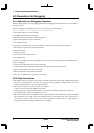
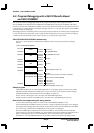
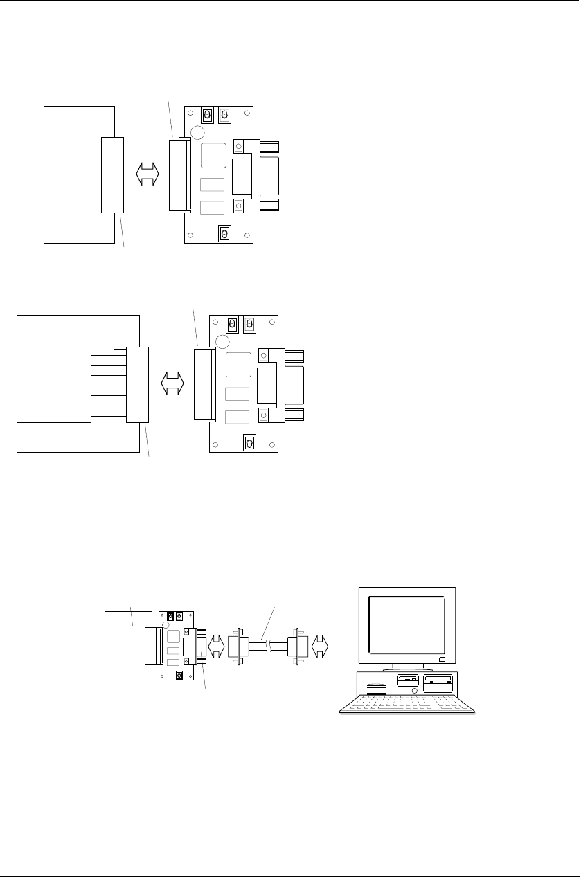
Connecting to a personal computer
Connect the S5U1C330MxD1 board to the COMx port connector (the port used for debugging) of the personal
computer with the RS232C cable supplied with the S5U1C330MxD1 package.
RS232C cable
(supplied with the S5U1C330MxD1 package)
COMx
RS232C connector (female)
(male) (female)
S5U1C33xxxDx/
target board
EPSON
Figure A.3.3 Connecting to a personal computer