


APPENDIX S5U1C330MXD1 BOARD
EPSON S1C33 FAMILY DEBUG MONITOR
OPERATION MANUAL
18
A.5 Program Debugging with a S5U1C33xxxDx Board
and S5U1C330M2S
This section describes the debugging procedure of the program on the target system configured with the
S5U1C330MxD1 board and the S5U1C33104Dx/S5U1C33209Dx board using the S5U1C330M2S. The sample
program for the S5U1C33104Dx/S5U1C33209Dx is used for the explanation. Further, the development tools in the
"S1C33 Family C Compiler Package" including the debugger (db33 ver. 1.72 or later) that supports S5U1C330M2S
should be installed for debugging.
The debugging function of the debug monitor can be tested using the sample file even when using a user target board
as well as the S5U1C33xxxDx board. Use the sample file after modifying the necessary parts such as the mapping
condition and the communication routines (refer to Section 2.4) according to the target system.
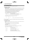
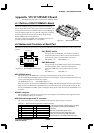
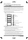
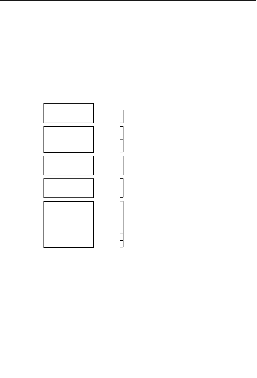
S5U1C33104Dx/S5U1C33209Dx address map
Figure A.5.1 shows the S5U1C33104Dx/S5U1C33209Dx memory map and the area used by the debug
monitor.
CPU: S1C33104/S1C33209
0xC1FFFF External ROM
128KB 0xC021FF Boot routine
0xC00000 0xC00000 S5U1C330M2S library
0x6FFFFF External RAM
1MB
0x6FFFFF
0x6FF640
S5U1C330M2S work area
0x600000
0x6FF63F
0x600000
Free area
0x2FFFFF Flash memory 0x2FFFFF
1MB Free area
0x200000 0x200000
0x04FFFF Built-in I/O 0x04FFFF
Control registers of built-in I/O
0x040000 0x040000
∗ Built-in RAM
S5U1C33104Dx: 6KB
∗
0x000030
Free area
∗: 0x17FF(S5U1C33104Dx), 0x1FFF(S5U1C33209Dx)
S5U1C33209Dx: 8KB 0x00002F
0x000010
Reserved area for S5U1C330M2S
0x00000C R0 stack area
0x000008 PC stack area
0x000000 0x000000 Debugging vector
Figure A.5.1 S5U1C33104Dx/S5U1C33209Dx memory map
Sample program
"\dmt33004\sample\led.srf" and "dmt33004\sample\led2.srf" are sample programs for the S5U1C33104Dx
that blinks the LED on the S5U1C33104Dx board. "led.srf" and "led2.srf" are created to be able to debug in
the RAM (0x600000~) and in the Flash memory (0x200000~), respectively.
For the contents of the program, refer to the source file (\dmt33004\sample\led.s).
Sample programs for the S5U1C33209Dx are also provided in the "\dmt33005\sample\" directory.
Boot routine and implementing the debug monitor
A boot routine and the debug monitor are written in the external ROM (0xC00000~) on the
S5U1C33104Dx/S5U1C33209Dx in advance. Therefore, a sample program/target program can be debugged
by loading from the debugger db33 to the RAM or the Flash memory on the S5U1C33104Dx/S5U1C33209Dx.
It is not necessary to link the S5U1C330M2S library to the program to be debugged.
The S5U1C330M2S library implemented in the S5U1C33104Dx is "mon33ch1.lib" that uses the built-in
serial interface Ch.1. The S5U1C33209Dx uses "mon33ch0.lib" that supports the built-in serial interface Ch.0.
Refer to "\dmt33004\m3s_boot.s" and "\dmt33005\m3s_boot.s" for the boot routine, "\dmt33004\
dmt33004.cm" and "dmt33005\dmt33005.cm" for the linker commands to implement the debug monitor.