(3)
Electrical characteristics
(a) Signal output current:
Maximum
-1 A (510 ms or less)
(b) Power ‘supply output voltage: 24 VDC (typical)
(c) Power supply output current:
Maximum 1A (510 ms or less)
(d) Output waveform:
Refer to Figure B-2.
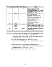
NOTE 1: These are not output
during
printing.
2: Drawer-kick drive signals L1 and L2 cannot be output at
the same time.
Drawer open/close signal
SW(+) signal level:
“LOW = 0 to 0.5 V
“HIGH” = 3 to 5 V
Printer side
User side
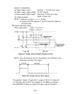
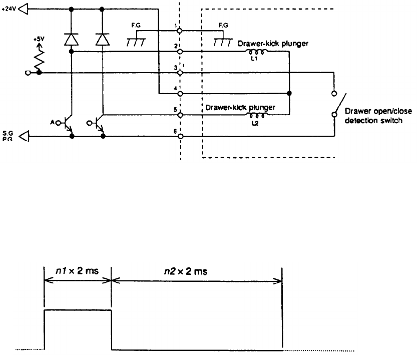
Figure El. Drawar kick-out Signal Interface Circuit
NOTE: Only the solenoid can be connected to the terminal of the
drawer-kick connector drive signal.
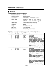
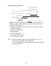
Figure B-2. Drawer kick-out Drive Signal
The waveform shown in Figure B-2. is output at Point A in Figure B-1 .
(n1 (ON time) and n2 (OFF time) depend on the
ESC p
command.)
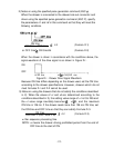
See APPENDIX D Notes on Using the Drawer kick-out Connector.
-65-


