


PoleVault Systems Installation • Optional Accessory Installation
2-30
Optional Accessory Installation — PPC 25
The Priority Page Controller (PPC 25) momentarily silences classroom audio whenever a page is made from a public
address (PA) system.
For detailed information, refer to the PPC 25 Installation Instructions, supplied with the device.
N
The Priority Page Controller works with traditional 25 V or 70 V and 4/8 ohm PA systems. It is not designed
for, and may not work properly with, two-way intercoms, or systems that are IP-based or use digital clocks.
Priority Page Controller included parts:
Priority Page Controller•
Priority Page Sensor•
UL-compliant junction box with a cable clamp and a lid•
35' (10.7 m) of sensor cable•
Y-cable for sharing power with another unit•
Installation Procedure
W
All structural steps, anchoring, and
electrical installation should be performed
by qualified personnel in accordance with
local and national building codes, fire and
safety codes, and/or local and national
electrical codes.
To meet the plenum rating requirement, the Priority Page
Sensor assembly must be installed in a UL-compliant
junction box with a cover and all cables to and from the
sensor must be plenum rated.
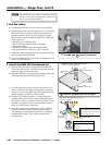
1. Choose suitable locations for the controller and sensor. The
controller must be located close to the PVS 204SA and its
power supply. The sensor must be located near, and in series
with, the speakers.
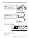
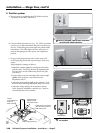
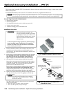
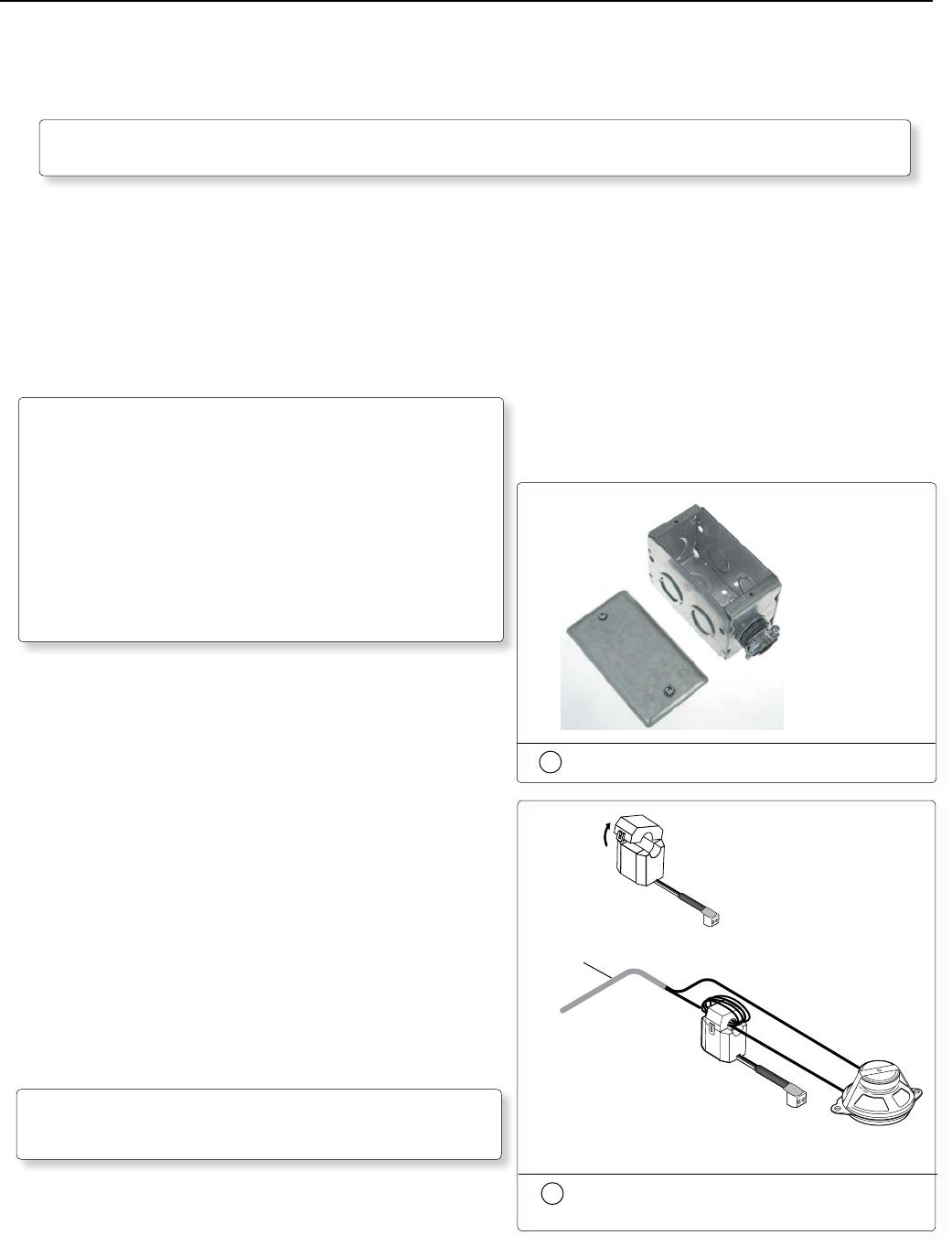
2. If the sensor is to be located in a plenum space, the junction
box (provided) can be used. Knock out an opening at one
end of the junction box and attach the cable clamp (see
figure at right). Secure the box where the sensor will go.
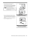
3. Disconnect the PA system speaker cable from the speaker.
Remove the outer protective jacket from the speaker cable to
expose the two speaker wires from the sensor to the speaker
(as shown at right). Do not remove the inner protective
jackets that cover the individual wires.
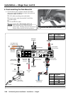
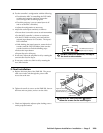
If the sensor is to be located in a plenum space, feed a loop
of one of the exposed speaker wires through the cable
clamp into the junction box. The other wire must bypass
the sensor to be connected later directly to the speaker.
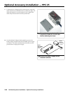
4. Open the top of the Priority Page Sensor and loop the speaker
wire that is inside the junction box, tightly around the top
part of the sensor.
N
Loop only one of the speaker wires around the
sensor cover. Do not loop both wires. Polarity
need not be observed.
The other speaker wire must bypass the sensor and connect
directly to the speaker.
• For a 25 V or 70 V system, wrap 5 to 8 loops.
• For a 4/8 ohm system, wrap 2 to 4 loops.
Open the
Page Sensor
Ceiling Mounted
Paging Speaker
Priority
Page
Sensor
Strip plenum jacket from
speaker cable to reveal
two speaker wires.
Speaker Cable with
Plenum Jacket Intact
4
Open the sensor and loop a wire
around the sensor
2
UL-compliant junction box and cover