


2-31
PoleVault Systems Installation • Optional Accessory Installation
P
O
WER
CNO
PA
G
IN
G
S
ENSO
R
OUT
T
IME
RELAY
S
EN
S
ITIVITY
1
2
V
0.5
A
MAX
ON
1
2
L
R
R
S
-232 ML
C/
IR
4
/8
O
hms
A
MPLIFIED OUTPUT
S
VOL/MUTE
Tx
A
B
C
Rx
I
R 12V
10V
Priority Page
Controller
PVS 204SA
6
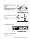
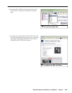
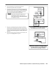
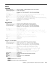
Connect the Priority Page Controller to
the Vol/Mute port on the switcher
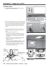
5. Close and latch the top of the Priority Page Sensor.
Reconnect the speaker cable to the speaker.
6. Cut an 18" (45 cm) section from the unterminated end of the
supplied blue sensor cable. Use it to connect the Relay Out
port on the Priority Page Controller to the Mute and Ground
pins on the PoleVault PVS 204SA Vol/Mute port (see the
figure at right). Polarity need not be observed.
N
Do not connect either of the outputs from the
Priority Page Controller to the 10V port on
the PVS 204SA switcher. The output relay must
connect only to the PVS 204SA switcher and not
to a MediaLink controller.
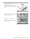
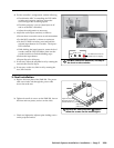
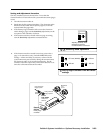
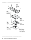
7. Strip 3/16" of insulation from each conductor on the bare
wire end of the remaining blue sensor cable. Do not tin the
leads. Feed the wire into the junction box (clamping it down
if necessary) and connect the wires to the 2-pole captive screw
connector on the Priority Page Sensor. Polarity need not be
observed.
8. Route the connector end to the Priority Page Controller, and
plug it into the Paging Sensor receptacle.
PO
WER
CNO
PA
G
IN
G
S
EN
SOR
OUT
TIME
RELAY
SENSITIVITY
1
2
V
0.5
A
MAX
ON
1
2
Page
Sensor
Priority Page
Controller
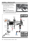
7
Wire the connector on the Page sensor
and
8
connect it to the Paging Sensor
port on the Priority Page Controller.