1
TeamWork
™
Kits • Installation Guide
TeamWork 400 and TeamWork 600 Kits
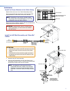
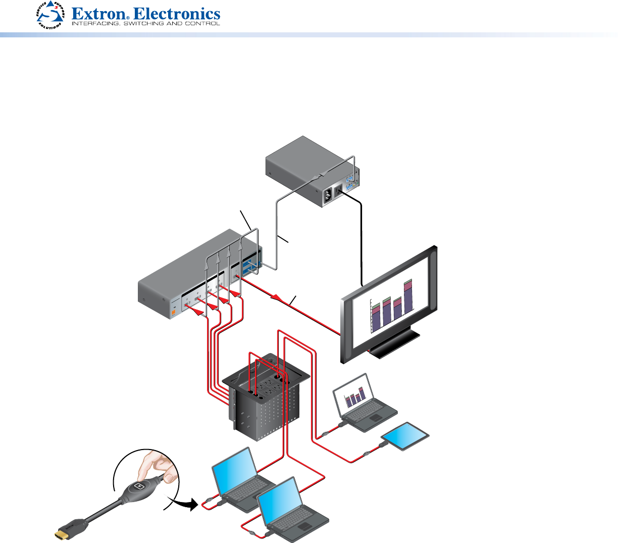
The TeamWork 400 and TeamWork 600 kits consist of an HDMI switcher, system controller, Cable Cubby
®
, and cables packaged
together as a complete system that, in most cases, requires no conguration.
0.
3A MAX
POWER
12V
1
Tx
Rx
RS-232 AUTO
2 3 4
INPUTSSW4 HDMI
REMOTE
12
3
4G
CONTACT
1234+V
TALLYOUT
OUTPUT
Extron
SHARE
100-120V 50/60Hz
12A MAX POWER OUTPUT 12A MAX
LAN
COM
TX
IN SG
+5VRX
INPUT
IR
US
LISTED 1 7TT
AUDIO/VIDEO
APARATUS
®
Extron
Cable Cubby 800
Cable Access Enclosure
100-240V/ 5A MAX
100-240V/ 5A MAX
100-240V/ 5A MAX
Regional Sales
0
30
60
90
120
150
SOUTH
NORTH
EAST
WEST
Extron
SW4 HDMI
Switcher
Extron
IPL T PC1
System Controller
RS-232
Control Cable
Extron
HDMI Pro Cable
HDMI Video
Flat Panel
Display w/ Integrated
Speakers
Extron “Show Me” Cables
Flat Panel
AC Cord
Contact Closure
& Tally
Regional Sales
0
30
60
90
120
150
SOUTH
NORTH
EAST
WEST
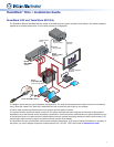
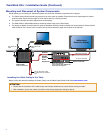
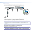
The diagram above shows a typical TeamWork 400 application. The input devices (laptops and a tablet) connect to the switcher,
using “Show Me” cables. The “Show Me” cables allow the user to select the active input on the switcher.
A control cable connects the RS-232 ports on the switcher and the system controller.
The system controller powers the display on and off. The system controller has been congured so that when a video signal is
detected on any of the switcher inputs, the display is powered on. A 30 second timer is started when no signal is detected on any
of the switcher inputs. If an active source is detected before the timer expires, the display remains on and the timer is reset. If 30
seconds pass without an active signal, the system controller powers off the display.
The TeamWork kits work, as described, without further software conguration. If you need to change the behavior or operation of
the system, you must congure the system controller (see the IPL T PC1/IPL T PC1i User Guide at
www.extron.com).


