


TeamWork Kits • Installation Guide (Continued)
10
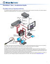
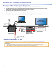
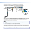
Connect the Switcher to the Display Device
Connect the switcher HDMI output to the HDMI input of the display device, using the provided cable. Do not use HDMI to DVI
adapters. If necessary, see the user guide for the display device.
Connect the Display to the System Controller
Connect the power cord from the display device to the power output receptacle of the system controller. TeamWork systems work
by controlling the AC power to the display.
ATTENTION: If you are using the IPL T PC1i (International TeamWork kits) you must replace the power plug on the display
with the provided adapter. (For instructions, see page 3.)
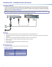
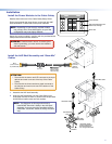
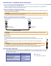
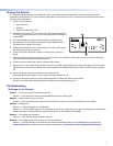
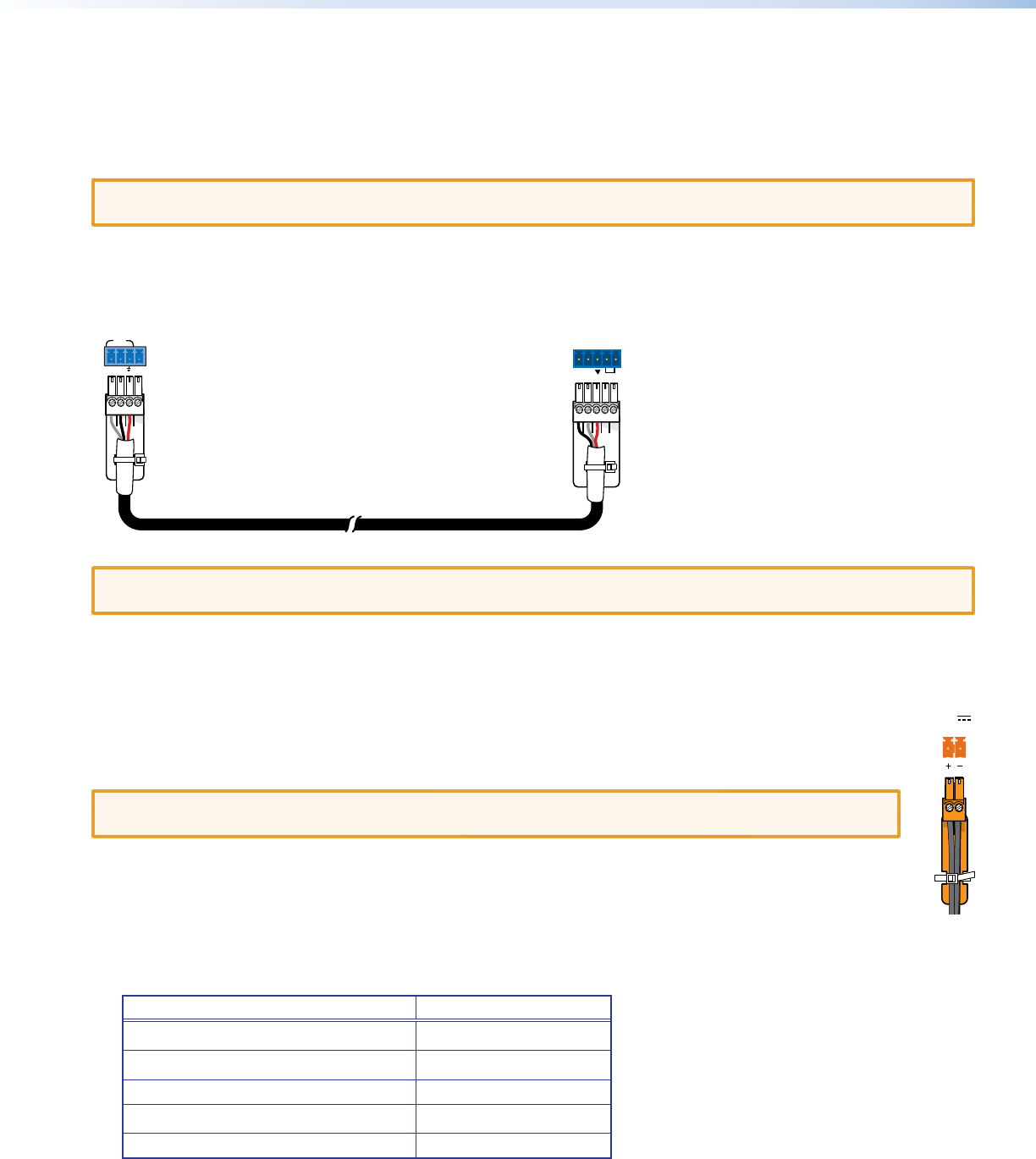
Connect the System Controller to the Switcher
Connect the COM port of the system controller to the RS-232 port on the switcher with the provided control cable.
System Controller
(IPL T PC1)
COM
TX +5VRX
Switcher
(SW4 HDMI)
TxRx
RS-232 AUTO
5-pole connector
(to switcher)
4-pole connector
(to system controller)
Switcher Control Cable
ATTENTION: The two ends of the RS-232 control cable are different. One has a 4pole connector, the other has a 5pole
connector.
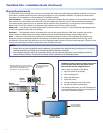
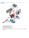
Connect Power
The system controller uses an internal power supply. Connect the power cord to a wall outlet.
The TeamWork 600 systems use a 6 input switcher with an internal power supply. Connect the power cord to a wall
outlet.
The TeamWork 400 systems use a 4 input switcher with a 12 VDC, 1 A power supply, which is provided with the
switcher.
ATTENTION: Do not connect the power supply to the SW4 HDMI switcher until you have read the Attention
notications in the “Wiring the Power Supply” section of the SW HDMI Series User Guide.
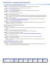
The optional TeamWork VGA kit also includes a 12 VDC, 1 A power supply for the analog to digital converter.
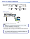
Converter SIS
™
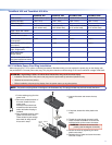
Commands
The following features have been pre-congured on the RGB-HDMI 300 A. The values should be re-entered if they have been
erased by a factory reset (see the RGB-DVI 300 and RGB-HDMI 300 (A) User Guide at
www.extron.com for a complete
explanation of SIS commands).
Feature SIS Command
Set output signal resolution to 1080p
E24*8RATE}
Enable power save mode
E1PSAV}
Enable Auto-Image 1*1A
Disable auto memories
E0AMEM}
Enable front panel security lockout 1X
0.4A MAX
POWER
12V
E = Escape key
} = Carriage return (no line feed)