TeamWork Kits • Installation Guide (Continued)
6
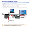
Mounting and Placement of System Components
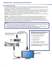
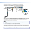
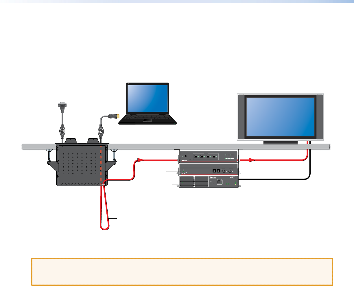
Decide where you will install your TeamWork system and where the individual components will be placed.
z The Cable Cubby should provide easy access for as many users as possible. Ensure that there is ample space for cables
under the table. Ensure that the edge on which the lid opens is correctly oriented.
z The system controller should be placed close to the display.
z The SW4 HDMI (or SW6 HDMI) switcher should be placed close to the Cable Cubby.
z The analog-to-digital converter (with the optional TeamWork VGA kit) should be placed next to the switcher. Ensure that the
VGA connector can connect to the converter and the three-conductor pigtail can connect to the switcher.
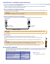
Shown mounted with
optional Extron UTS 100/UTS 150
Under Table Shelf System.
Secure “Show Me” Cable
to Cable Cubby and create a
loop.
HDMI Video to Display
Extron
Cable Cubby
Cable Access Enclosure
HDMI ”Show Me”
Cable
VGA “Show Me”
Cable
IPL T PC1
R
100
TX
RX
INPUT
IR
LINK
ACT
POWER
System Controller
Switcher
VGA Kit
(optional)
Power
Supplies (2)
AC Power To Display
RGB - HDMI 300 A
MENUENTER
ADJUST
CONFIG
SW4 HDMI
HDMI SWITCHER
1
IR
CONFIG
SIGNAL
INPUTS
INPUTS
OUTPUT
1 2 3 4
HDCP
2 3 4
AUTO
SWITCH
1080p Native
Resolution Display
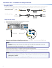
Installing the Cable Cubby in the Table
Before cutting the table and installing the Cable Cubby, see the Cable Cubby Setup Guide (see www.extron.com).
ATTENTION:
• Ensure that the orientation of the cable cubby and the hole dimensions are correct before cutting the table.
• After installation, secure the cables to avoid them becoming tangled (see the gure above).


