


7
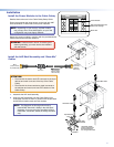
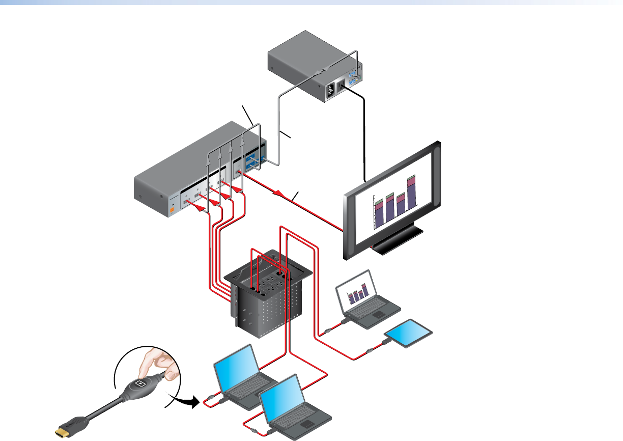
Cabling
Extron
SHARE
0.3A
M
AX
POWER
1
2V
1
Tx
Rx
RS-232 AUTO
2 3 4
INPUTSSW4 HDMI
REMOTE
1234G
CONTACT
1234+V
TALLYOUT
OUTPUT
100-120V 50/60Hz
12A MAX POWER OUTPUT 12A MAX
LAN
COM
TX
IN S
G
+5VRX
INPUT
IR
US
LISTED 1 7TT
AUDIO/VIDEO
APARATUS
®
Extron
Cable Cubby 800
Cable Access Enclosure
100-240V/ 5A MAX
100-240V/ 5A MAX
100-240V/ 5A MAX
Regional Sales
0
30
60
90
120
150
SOUTH
NORTH
EAST
WEST
Extron
SW4 HDMI
Switcher
Extron
IPL T PC1
System Controller
RS-232
Control Cable
Extron
HDMI Pro Cable
HDMI Video
a
b
c
d
e
f
f
Flat Panel
Display w/ Integrated
Speakers
Extron “Show Me” Cables
Flat Panel
AC Cord
Contact Closure
& Tally
Regional Sales
0
30
60
90
120
150
SOUTH
NORTH
EAST
WEST
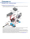
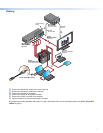
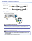
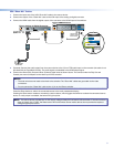
a Connect the “Show Me” cables to the source devices.
b Connect the “Show Me” cables to the switcher.
c Connect the switcher to the display.
d Connect the display to the system controller.
e Connect the system controller to the switcher.
f Connect power to the switcher and system controller.
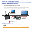
This diagram shows the TeamWork 400 system. To add a TeamWork VGA kit to the TeamWork system, see
VGA “Show Me”
Cables on page 9.