


Extron • Model 8 PLUS & Model 10 PLUS Switchers • User’s Manual Page 2-2
12345678910
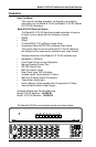
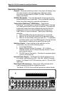
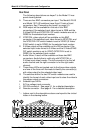
Rear Panel
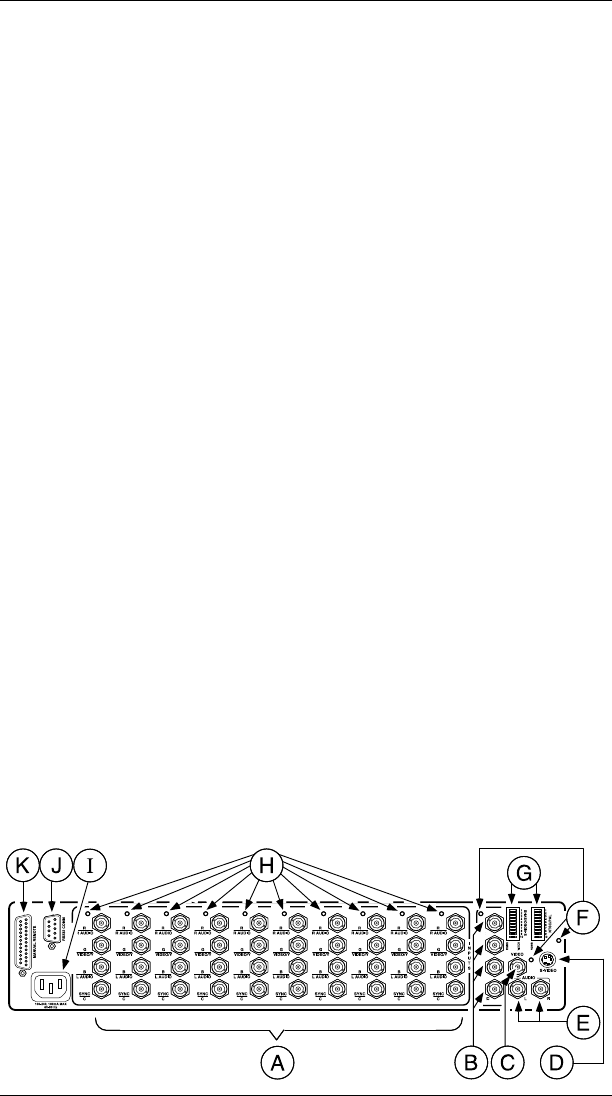
The following descriptions are keyed* to the Model 10 rear
panel drawing below.
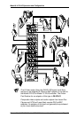
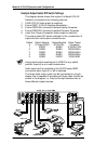
A There are four BNC connectors per input. The Model 8 PLUS
and Model 10 PLUS switchers have 8 and 10 sets of input
connectors. See "Connecting the Inputs" on page 2-3.
B RGB output will be available on this set of four BNC
connectors if the selected input video format is RGB and the
S-Video/SVHS and NTSC/PAL DIP switch modules are set to
RGBS for the selected input number.
C NTSC/PAL video output will be available on this BNC
connector if the selected input video format is NTSC/PAL and
the NTSC/PAL DIP switch module is set to VIDEO (S-Video/
SVHS switch is set to RGBS) for the selected input number.
D S-Video output will be available on this DIN connector if the
selected input video format is S-Video and the S-Video/SVHS
DIP switch module is set to VIDEO (NTSC/PAL is set to
RGBS) for the selected input number.
E Audio follow, if used, will be available on these two BNC
connectors. Audio follow is valid only with NTSC/PAL or
S-Video input video formats. The left connector is for the left
audio channel and the right connector is for the right audio
channel.
F These three LEDs are located next to the three video outputs
and one of the three will illuminate to identify the connector(s)
with video output for the selected video input.
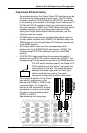
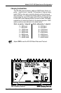
G The switches within the two DIP switch modules are used to
identify the format of each video input and to steer the video to
the proper output connectors.
H Selected input LEDs.
I AC line voltage input connector.
J RS-232 connector - See page 3-1 for a detailed description.
K Remote connector - See page A-1 for a detailed description.
* – Letters next to the descriptions above are keyed to the circled
letters in the drawing below.
Model 8/10 PLUS Operation and Configuration