


Extron • Model 8 PLUS & Model 10 PLUS Switchers • User’s Manual
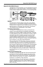
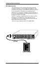
MANUAL REMOTE Connector
The MANUAL REMOTE connector provides
a way to control the Model 8/10 PLUS
switchers using Extron or third party remote
control devices.
Extron Remote Control devices which are
compatible with the Model 8/10 Switchers
are the KP-10 and IR-10 which are covered
on the following pages.
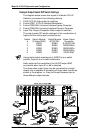
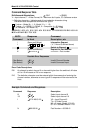
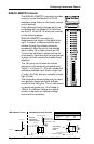
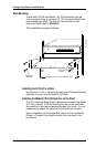
MANUAL REMOTE connector pin
assignments are shown in the table to the
right. To select a different switcher input
number through the remote connector,
momentarily short the pin for the desired
input number (#) to logic ground (pin 25).
To force the switcher to select that input #
continuously, leave the short to logic ground
in place, this will override front panel input
selection.
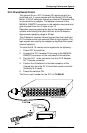
The Tally pins can be used for remote
indication of the switcher's selected input.
Tally #1 - #10 (pins 14 - 23) will indicate the
switcher's selected input # with a logic low
(0 volts), the Tally pins are normally at logic
high (5 volts).
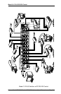
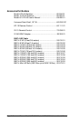
The schematics shown below may be used
as a guide to design and build indicator
circuits for the Tally pins. The +5 volt source
on remote connector pin 13 is limited to
100mA, if a different voltage or a higher
current is required, an external voltage
source will be necessary.
Configuring Features and Options
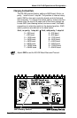
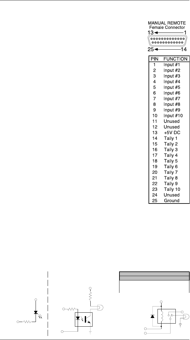
+5V (PIN 13)
EXTERNAL POWER
TALLY PIN
RESISTOR VALUE
DEPENDS ON CURRENT
REQUIREMENT OF LAM
P
330 Ohm
+5V (PIN 13)
TALLY PIN
LED
330 Ohm
LED Indicator Circuit
N/C
1N916
TALLY PIN
EXTERNAL POWER
+5V (PIN 13)
Using a Relay
& External
Power
Using an
Opto-isolator
& External Power
Page A-1
RECOMMENDED RELAYS
MANUFACTURER GENERAL LOW CURRENT
Aromat
ITT/Panasonic
Omron
DS2
R-Z-5C
G5Y
TQ
A5W
G6H
Incandescent Lamp Circuits