


DAV101CM, DAS101CM • Installation and Operation
2-5
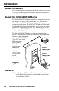
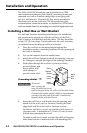
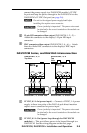
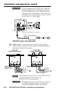
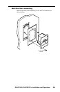
connect the power supply to a DAS101CM module’s 12 VDC
In port and loop the power through to the DAV101CM via the
DAS101CM’s 12 VDC Out port (see page 2-6).
N
Do not tin the stripped power supply leads before
installing the captive screw connector.
C
Correct polarity is important! The power wires must
be attached to the correct terminals or the module can
be damaged.
b
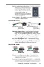
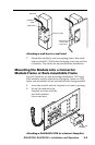
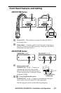
15-pin HD computer-video output (DAV101CM-1, -2, -5) —
Attach this connector to the display’s 15-pin HD input
connector.
c
BNC computer-video output (DAV101CM-3, -4, -6) — Attach
these ve male BNC connectors to the display’s BNC input
connectors.
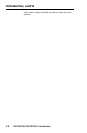
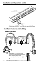
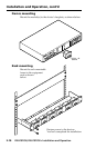
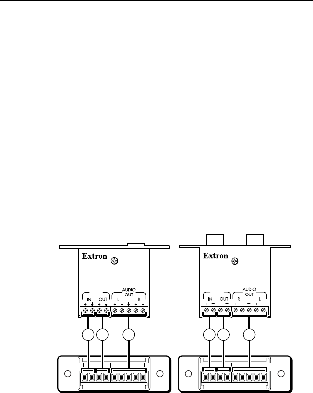
DAS101CM Series, and DAV-DAS interconnection
12
VDC
0.1 A
12
VDC
0.1 A
DAS101CM-1, -2, -5
Top View
DAS101CM-3, -4, -6
Top
View
DAS101CM-1, -2, -5 Rear View DAS101CM-3, -4, -6 Rear View
1 2 3 1 2 3
a
12 VDC, 0.1 A In (power input) — Connect a 12VDC, 1 A power
supply to these two poles of the DAS’s 4-pole direct insertion
captive screw connector for power input.
C
Correct polarity is important! The power wires must
be attached to the correct terminals or the module can
be damaged.
b
12 VDC, 0.1 A Out (power loop-through for DAV101CM
modules) — This port allows power to be looped through to a
DAV101CM. See the wiring diagram on the next page.